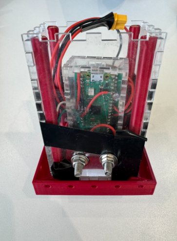
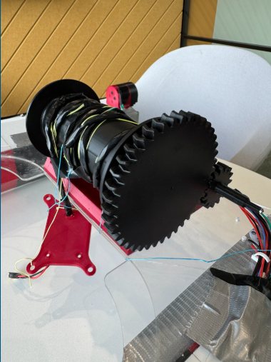
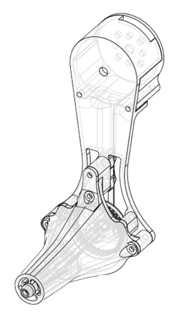
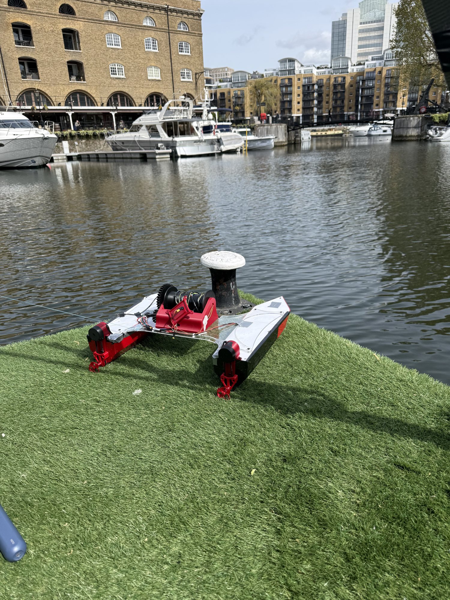
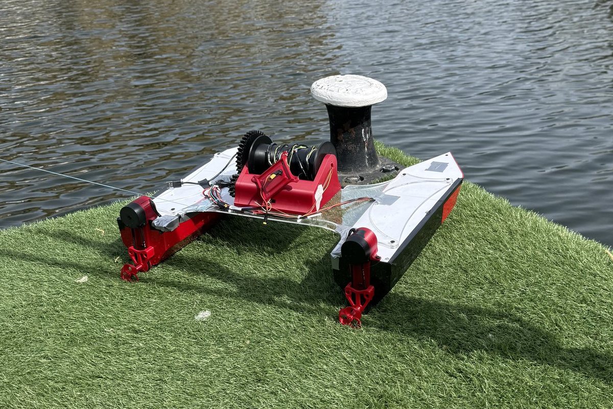
A twin-hull survey boat I co-founded with Matthew Hong. V1 drove itself to GPS waypoints at St Katharine Docks in London; V3, now in build, runs a Raspberry Pi 5 and a Teensy 4.1 on one custom carrier board.
Jan 2026 — PresentView Project
02Competition
Combat Robotics — Team DHM
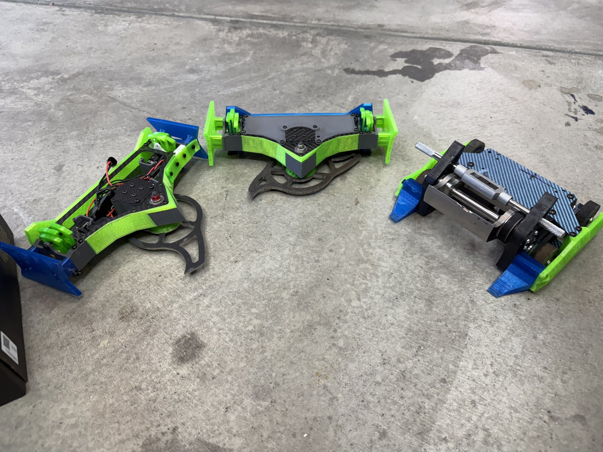
Around ten robots across five weight classes, designed in CAD and printed in-house. 4th nationally in Plastic Antweight; as a club, 16 podiums over 5 events.
2023 — 2025View
03In design
Adaptive Compliant Robotic Arm
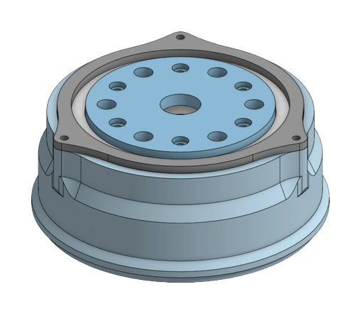
Five axes, three on cycloidal gearboxes checked in a simulator I built, a TPU gripper that reads its own grip force, and a ±0.25° positioning target. On paper so far.
2026 — in designView
04Mechatronics
Autonomous Maze-Navigating Robot
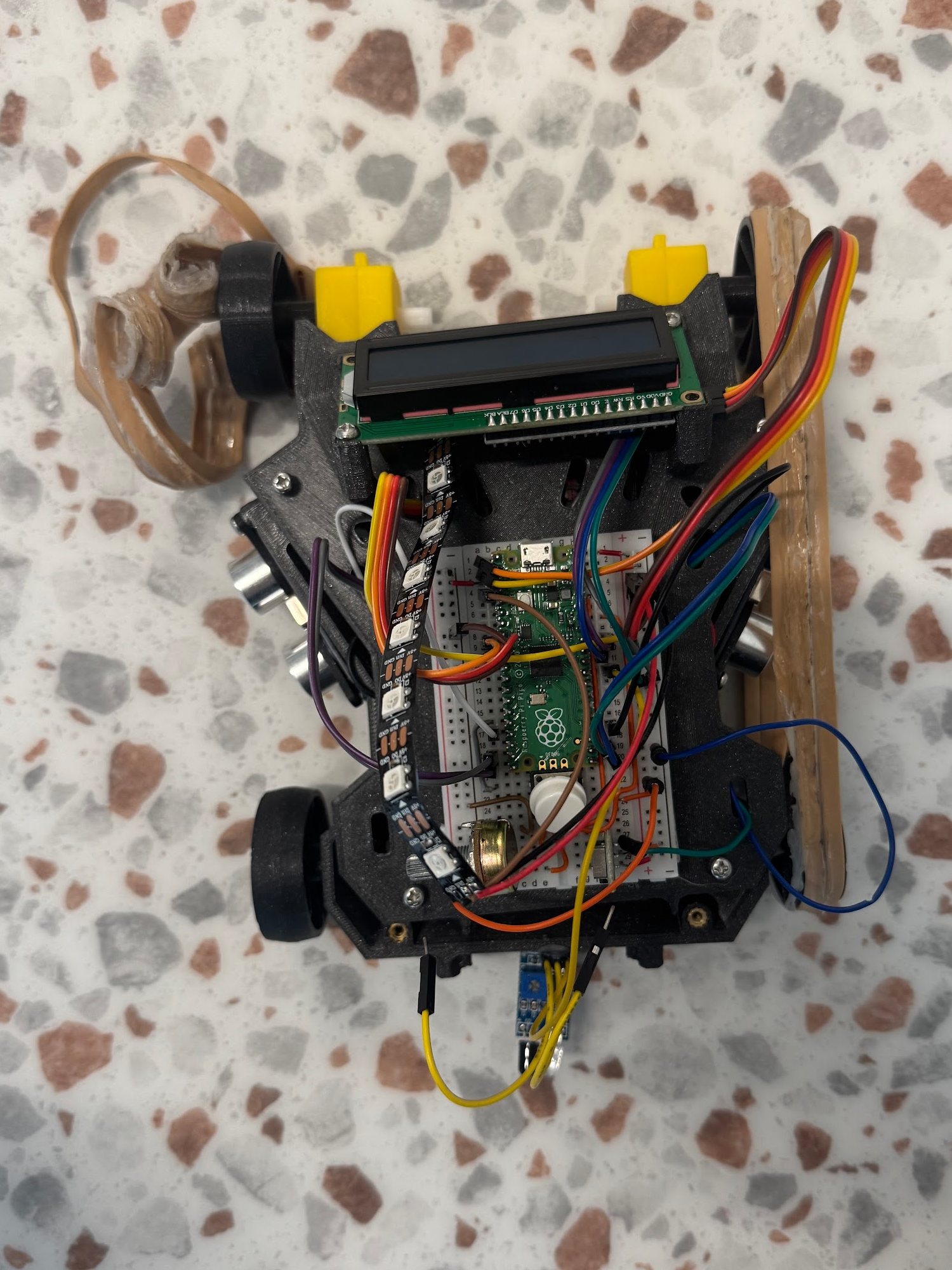
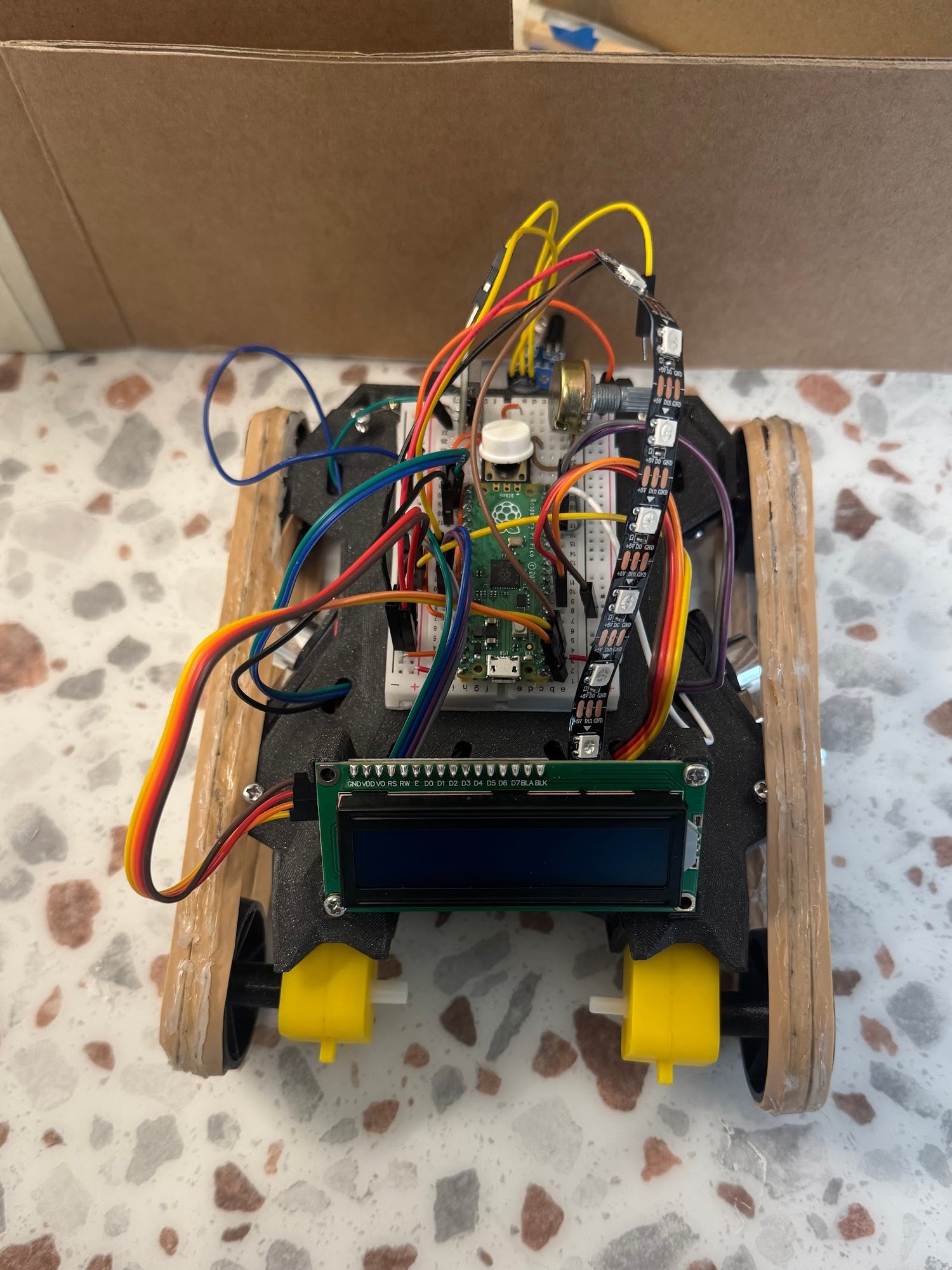
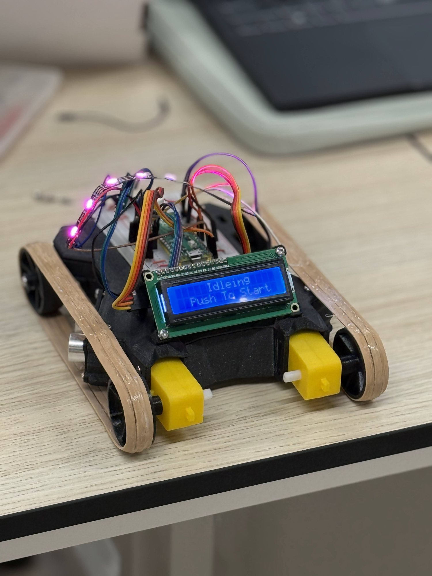
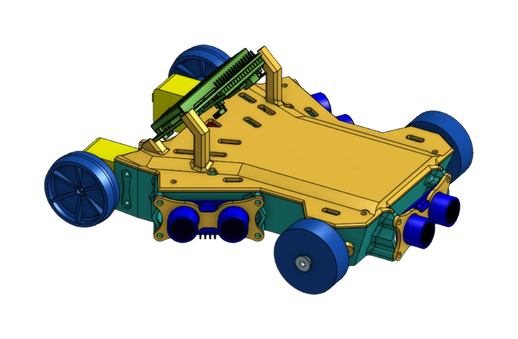
A 3D-printed tank-drive robot that steers itself through a maze off two angled ultrasonic sensors, with every task on one Raspberry Pi Pico.
Oct — Dec 2025View
05Assorted
Miscellaneous Builds
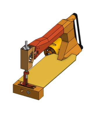
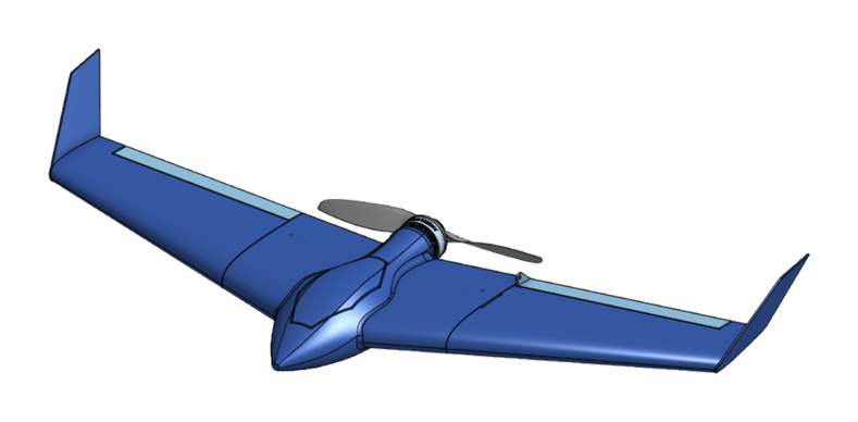
Ceramics tools published free for anyone to print, a 3D-printed RC plane, a sewing machine reverse-engineered in CAD, and printed climbing gear.
2023 — PresentView
Project 01 · Robotics & Embedded
Autonomous Environmental Survey Boat
Raspberry Pi 5Teensy 4.1Custom PCBCAN · VESCComputer VisionMicroPython
Status
V3 in build · V1 water-tested
Platform
Twin-hull catamaran · diff-drive
Compute · V3
Raspberry Pi 5 + Teensy 4.1
Sensing · V3
pH · DO · TDS · turbidity · temp · sonar depth
Comms · V3
4G LTE live map · RC override
Team
Co-founded with Matthew Hong
D.R.E.A.M.S (Data Recovery for Environmental And Marine Surveillance) is a modular twin-hull survey boat for mapping water quality in small bodies of water. Matthew Hong and I started it in our first year at Northeastern, and it is on its third generation: V3, in build now, pairs a Raspberry Pi 5 mission computer with a Teensy 4.1 real-time controller on one custom carrier board.
ResultV1, built in one semester in London, navigated to GPS waypoints on its own in a water test at St Katharine Docks, held a 433 MHz radio link of about 1 km to shore, and sampled at the bottom. V2 moved the brain to a Pi 5 with stereo vision and our first custom PCB, but was never fully built: bench tests exposed flaws in its motor control, power and safety design. V3 is the ground-up redesign; its carrier and pod boards are laid out and checked, and its hull is in CAD.
TeamI lead the hardware: the hull and CAD, the electronics and custom PCBs, and integrating it into one system. Matthew co-leads the mechanical and structural design, including a Van Veen grab sediment sampler delivered with a full drawing package and bill of materials, and handles planning and communications.
SoftwareThe software — firmware, vision pipeline and dashboards — was built with AI coding agents. I specified the architecture and did the integration and testing, not the line-by-line implementation.
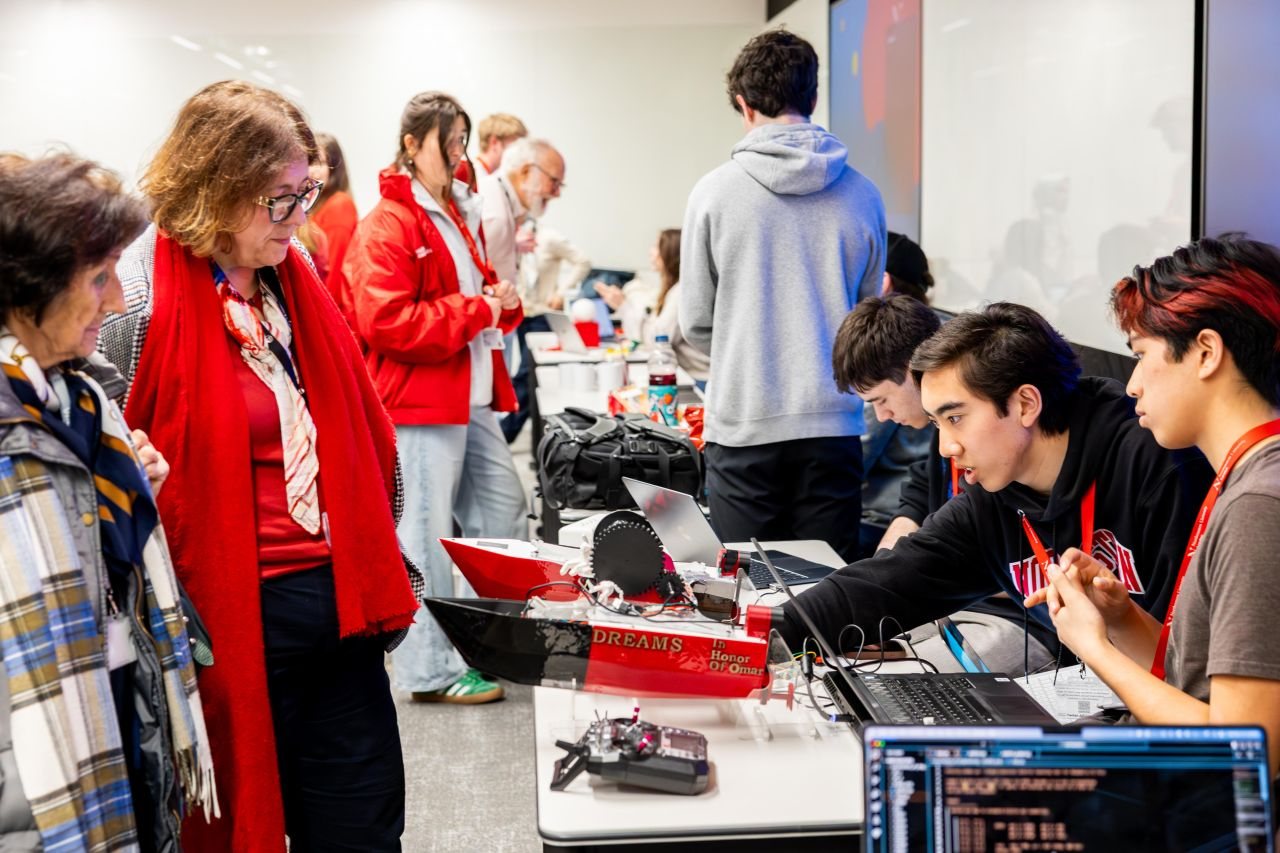
Showing D.R.E.A.M.S v1 to visitors at the inaugural Creators’ Showcase, Northeastern University London
Version 1 — field-testedConcept sketch, annotated CAD, the sensor pod, and the first build
Watch
Version 1 · Field-tested
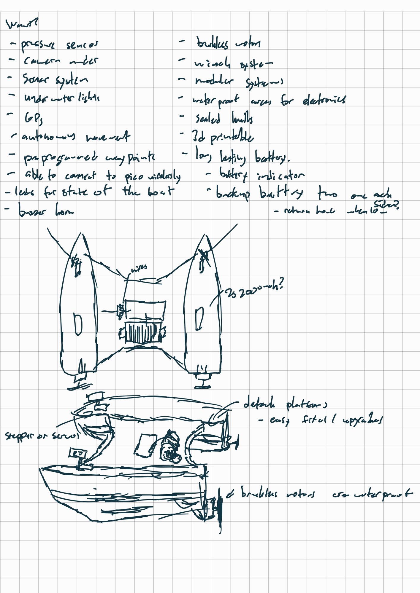
It started as a sketch: a stable, twin-hull platform that could carry sensitive instruments across open water and still sit calm enough to take clean readings.
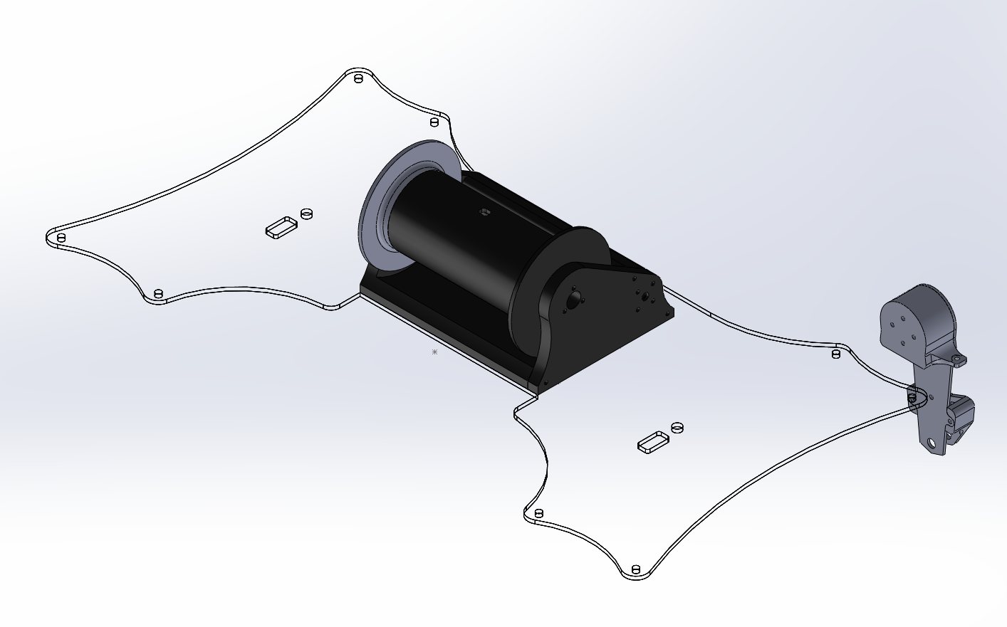
The dual-hull layout keeps the boat steady. Each pontoon houses waterproof compartments for batteries and electronics. The winch lowers an instrumented pod on a tethered slip ring until it registers bottom contact, then samples water temperature, conductivity (salinity), and light before retracting and moving to the next waypoint.
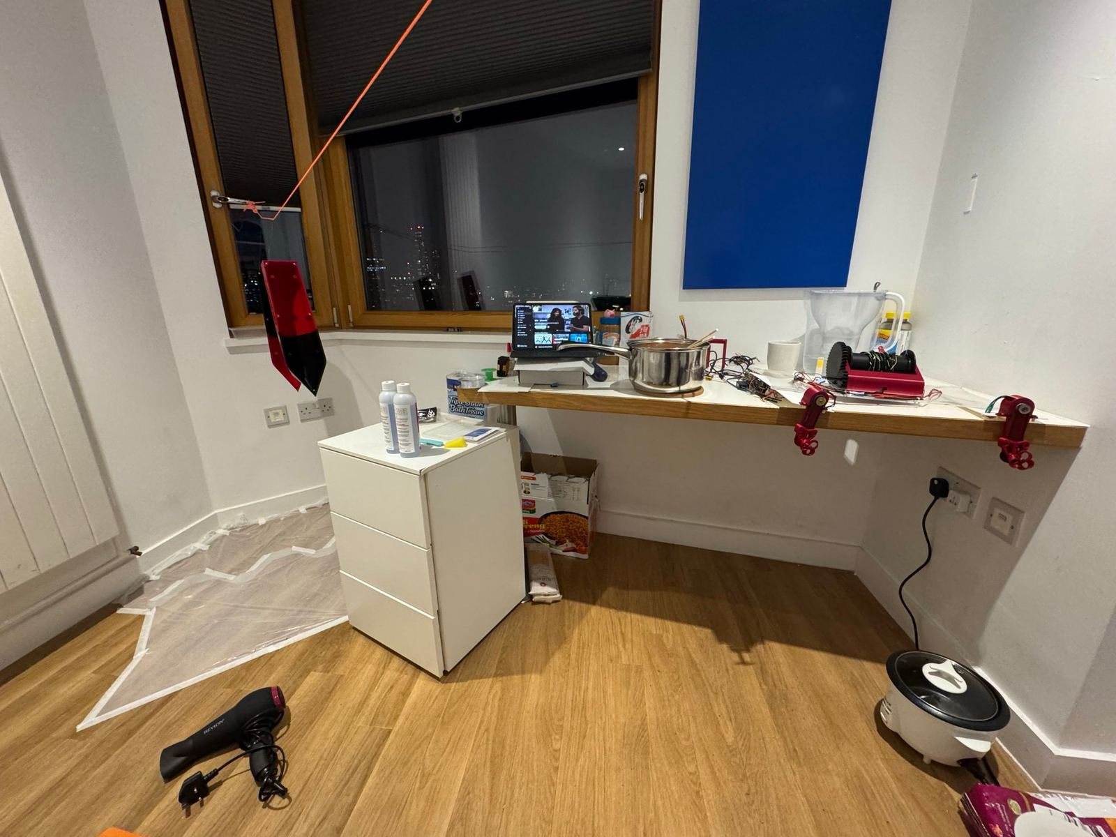
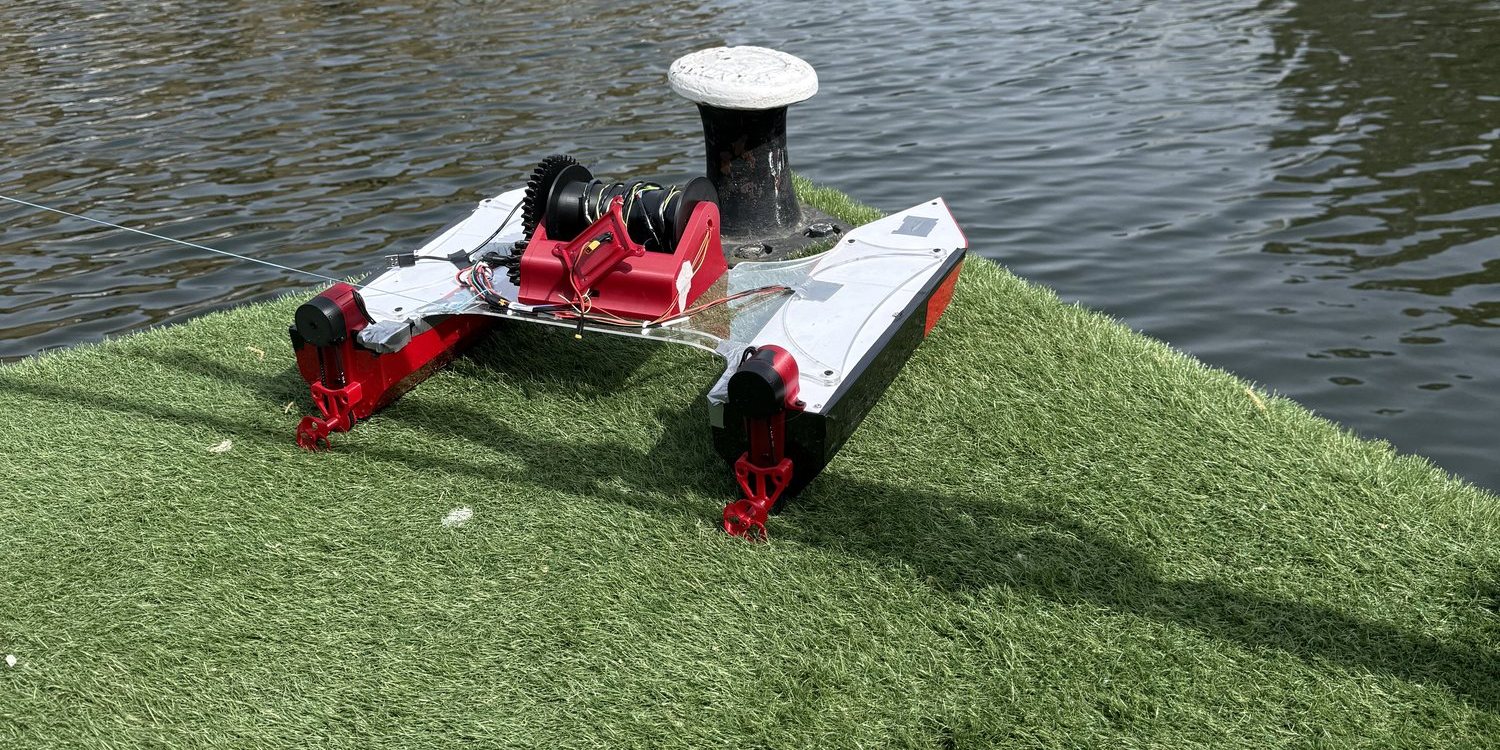
We built it in one semester of our first year, in London, with our room as the workshop, then took it to St Katharine Docks. In that water test it navigated to GPS waypoints on its own and held its radio link out to about 1 km.
First concept sketch — v1
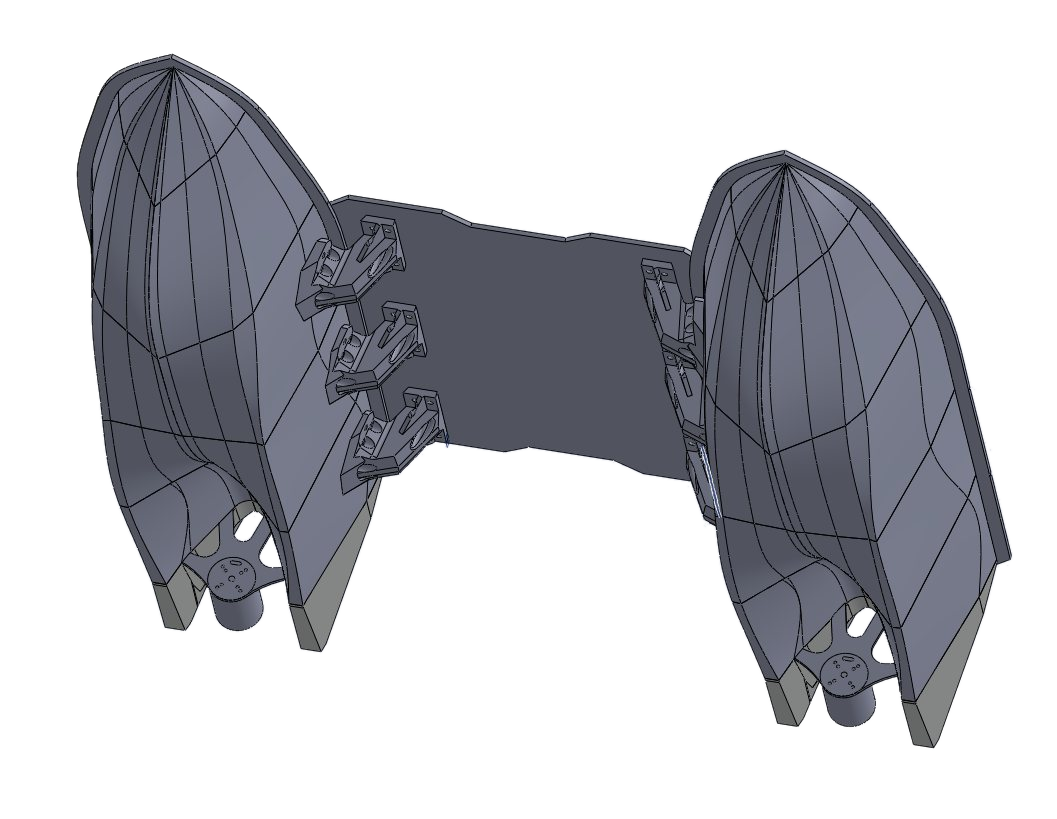
CAD · v1 platform
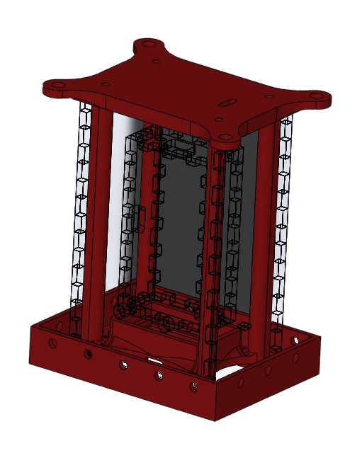
Catamaran bridgeSensor winchCAD — the bridge ties the two hulls together and carries the winch that lowers the sensor pod. (Hover or tap a marker.)
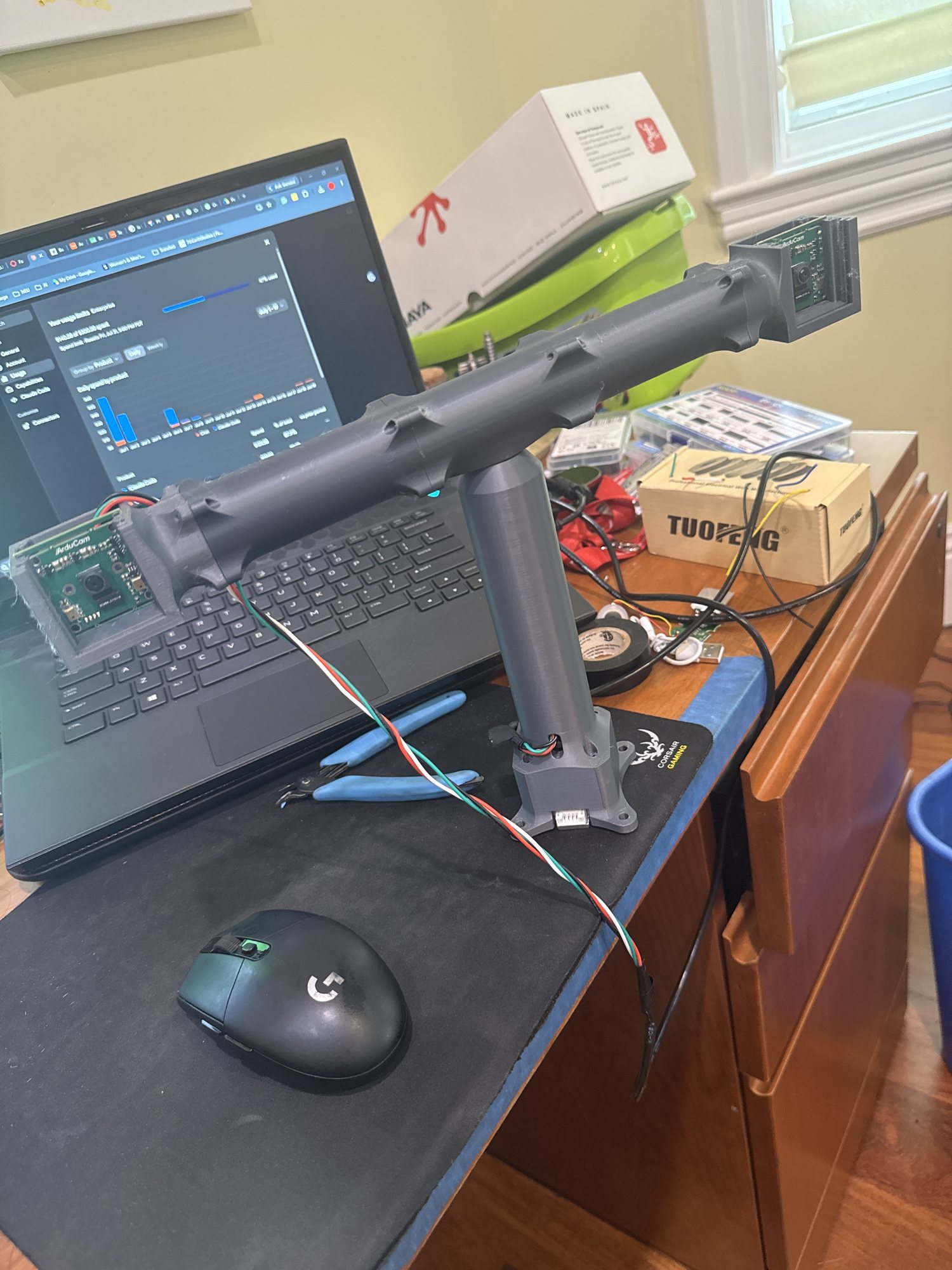
CAD — v1 sensor pod
v1 runs on three Raspberry Pi Picos in MicroPython. The boat controller alone juggles nine concurrent async tasks: GPS navigation, heading, dual-brushless drive, winch, mission logic, and safety. Alongside it run a shore operator station and the underwater pod.
They talk over an HC-12 433 MHz half-duplex radio with XOR-checksummed frames and burst/listen timing. The shore station loads a JSON mission, shows live telemetry, logs everything to CSV, and can e-stop or take manual control at any moment.
Printed & assembled
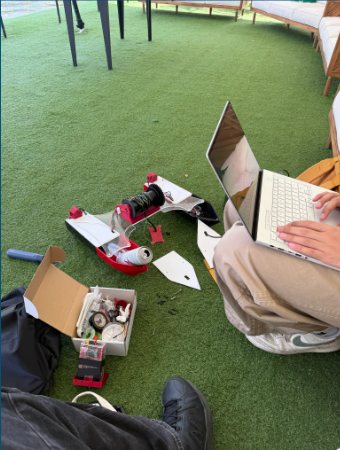
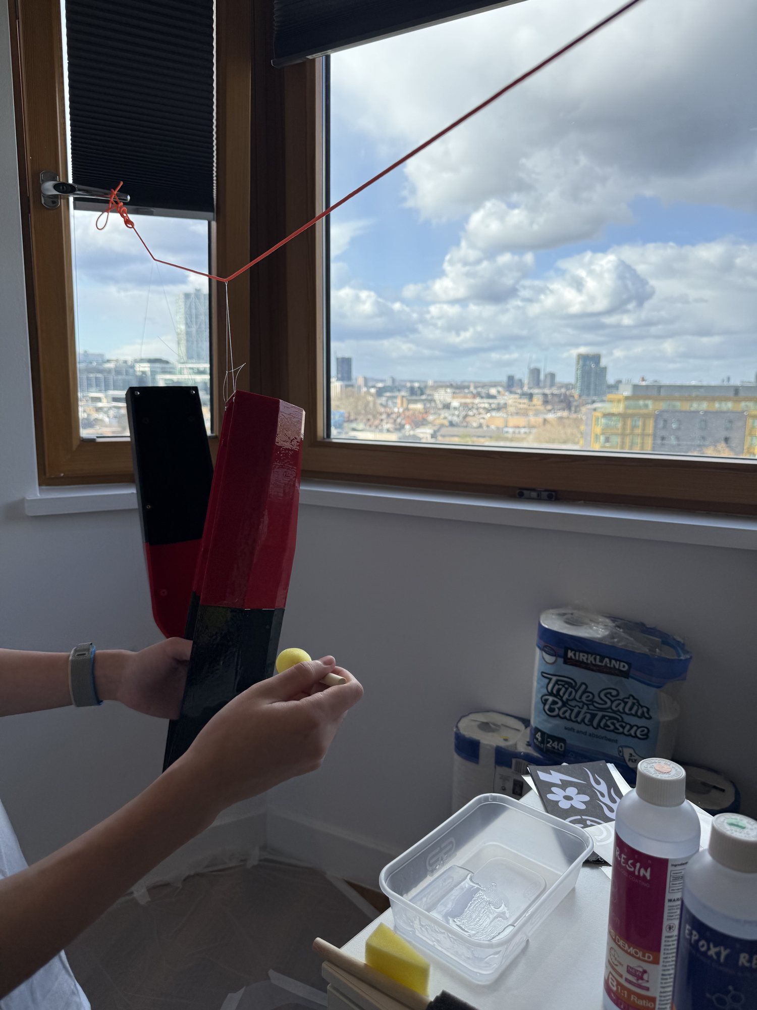
Getting ready to test outdoorsEpoxy-sealing the hullOur room in London, set up as the workshopSensor pod, printedSensor-deployment winchEarly jet-propulsion experiment — a dead end, but a useful one
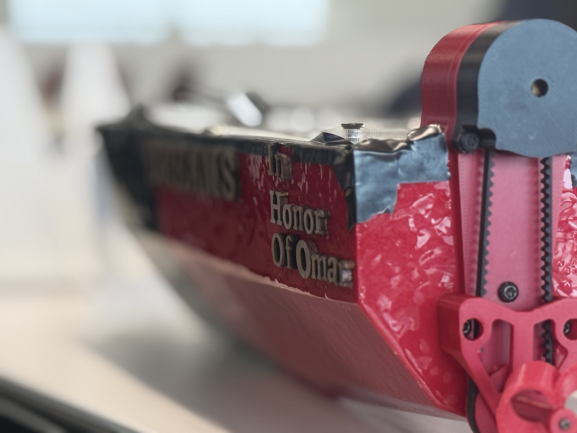
D.R.E.A.M.S v1, dedicated in honor of Omar. He helped us build it in London, and his name on the hull is our thanks.
Version 2 · Prototype
v1 proved the concept on the water and showed where it ran out of room. It couldn't see or avoid obstacles, the 433 MHz radio was short-range and half-duplex, the hand-wired loom was a tangle of failure points, and a PLA hull isn't built for long days on the water. v2 set out to answer each one:
M18 for electronics + winch · 12S LiPo drive planned
CAD — v2 hull geometry, refined for stability and flow
STEP 01 — HULL
A hull tuned for the water
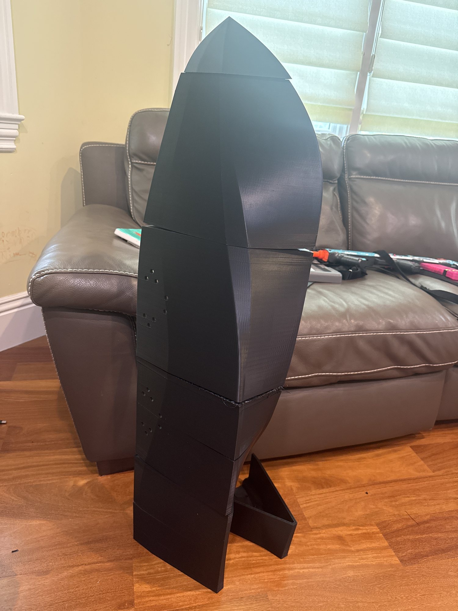
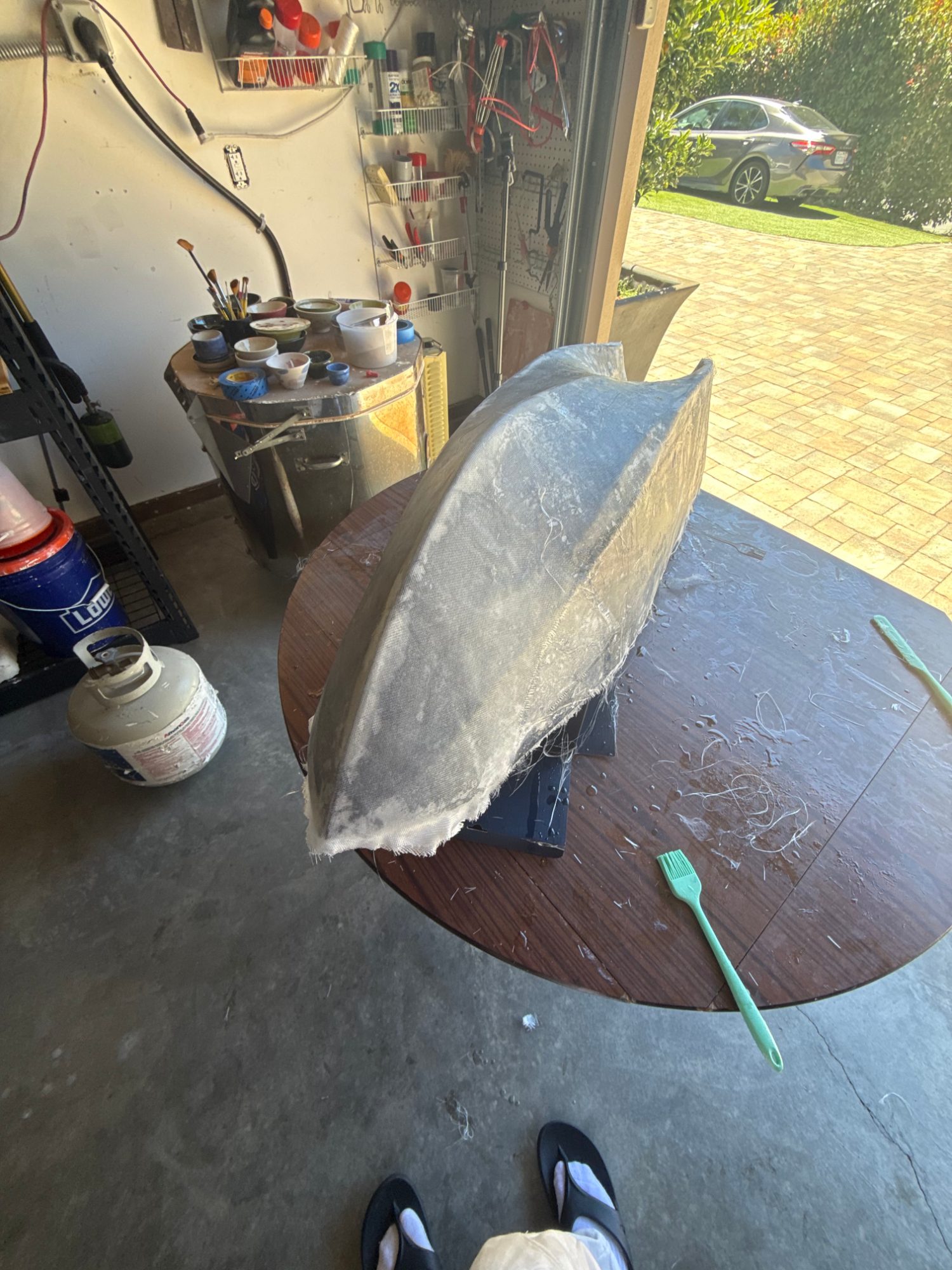
The twin-hull geometry is refined in CAD for stability and clean flow, then printed in bolt-together sections. v1 printed in PLA; v2 moves to ASA, which handles UV and weather where PLA goes soft and brittle, plus a fiberglass-and-epoxy skin for stiffness and water resistance.
STEP 02 — BOARD
One board instead of a harness
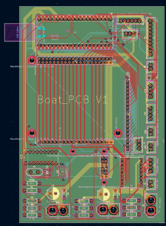
A custom KiCad carrier board replaces v1's hand-wired loom — consolidating three isolated battery domains, the two drive ESCs, and every sensor header in one place. Fewer failure points, faster to service.
STEP 03 — BRAIN
A Pi 5 that can see
A Raspberry Pi 5 runs navigation, the mission state machine, and a stereo-camera vision pipeline, with YOLO detection gated by a cheap water-anomaly screen. The two RP2040s stay down at the real-time layer, driving motors and reading sensors.
First printed section of the v2 hullA layer of fiberglass going on over the print — wetted out with epoxy for stiffness and water resistance
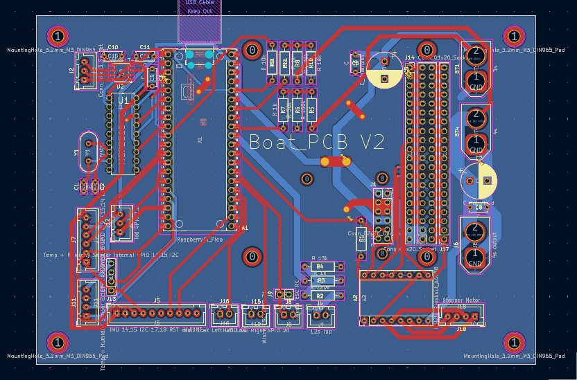
V2 custom PCB · rev 01 → rev 02
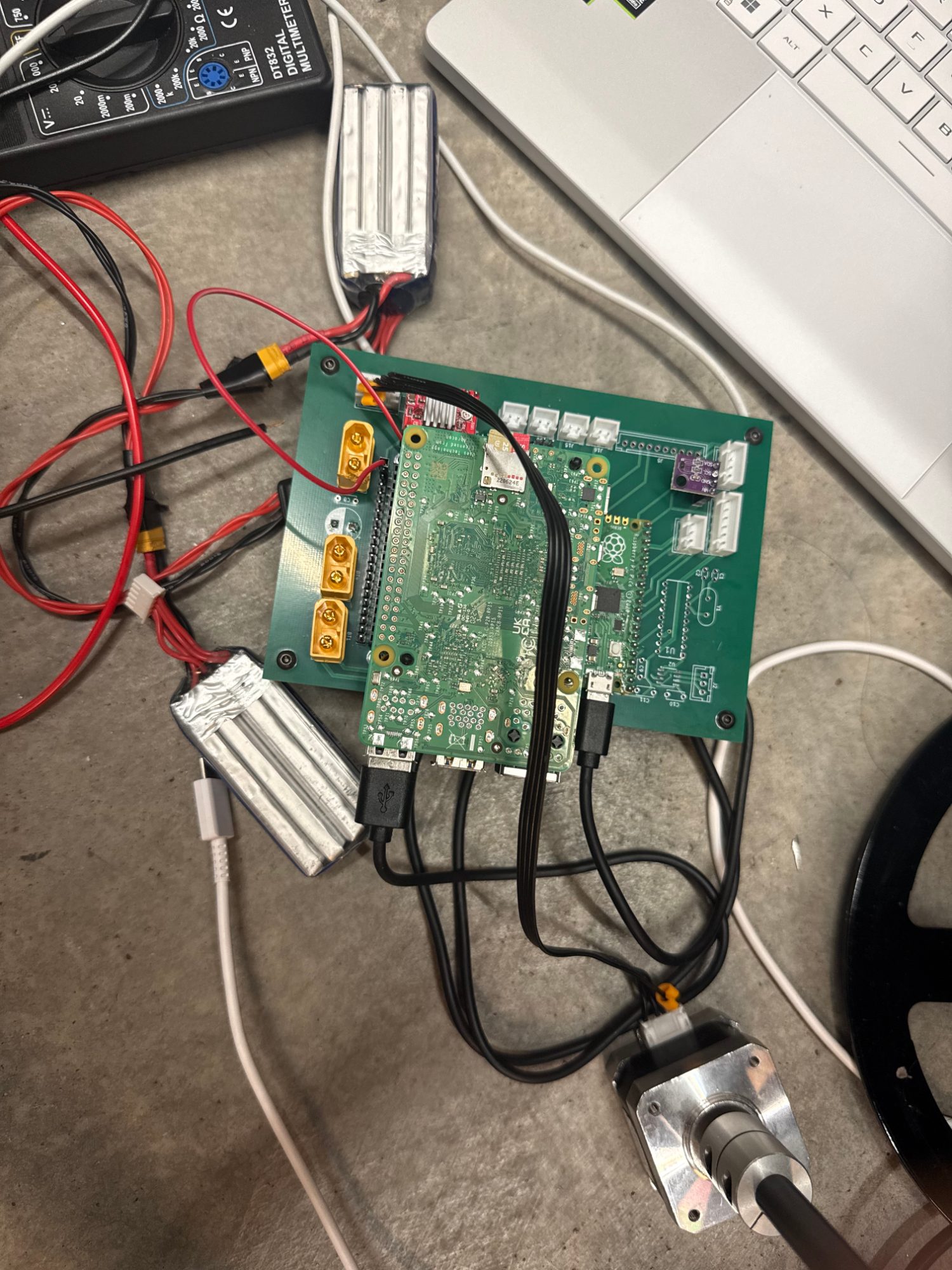
PCB — REV 01PCB — REV 02, consolidated power, radio, and sensor headersREV 02 on the bench during bring-up — Pi and RP2040 seated, battery domains and a motor wired in for testing
Stereo camera pair — per-object depth for vision-guided avoidance
Two USB cameras form a stereo pair. StereoSGBM turns the disparity into a real per-object distance, so a detected obstacle isn't just a box on a screen — it has a range.
A three-tier vision pipeline keeps it cheap: a constant water-anomaly screen wakes a YOLOv8-nano detector only when something's there, and a threat score decides what to track and when to steer away.
Watch · stereo tracking
The stereo pair picking me up and following me around the garage. Detection runs on the Pi itself, so the frame rate is low — but it is the first end-to-end look at the vision pipeline actually working.
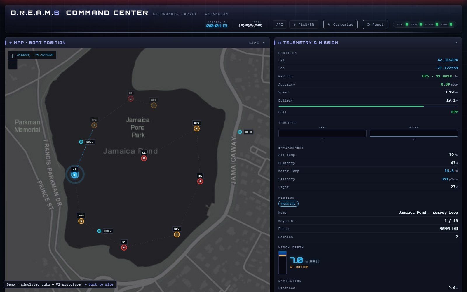
The command center ran on V2’s Pi 5: the mission map, live telemetry and the controls in one web page. It now runs in a browser with a simulated boat surveying a pond, so anyone can try it.
Then bench testing found the real problem. V2’s motor control, power and safety design weren’t reliable enough to put on the water, so instead of patching it we redesigned the whole system. V2 was never fully built, and V3 exists because of what it showed us.
The V2 command center, running a simulated survey on a pond
Version 3 · In build
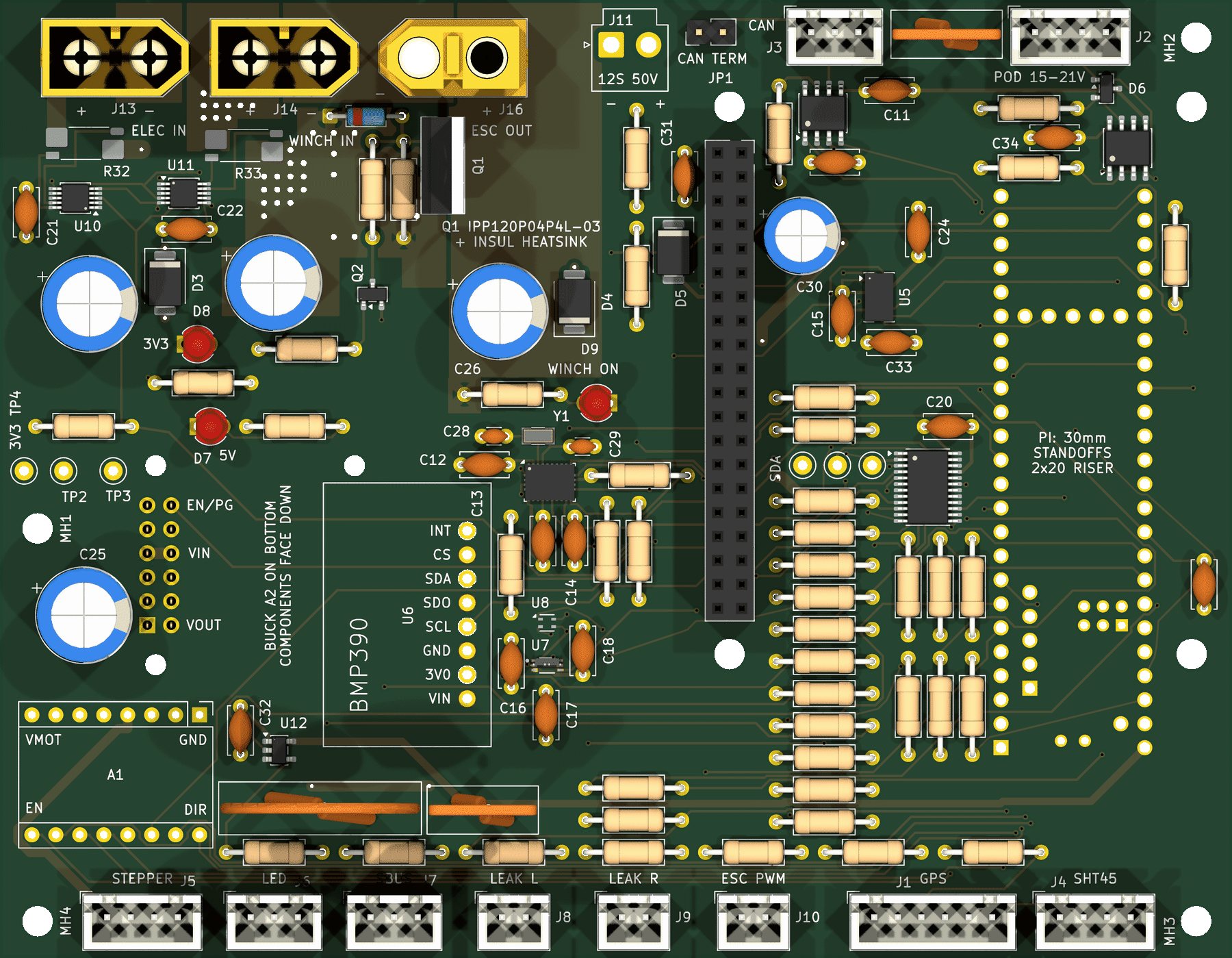
V3 splits the boat into a Raspberry Pi 5 mission computer and a Teensy 4.1 real-time controller, joined by one custom carrier board, with the sensors in a tethered pod. Its first job is narrower than V2’s on purpose: drive itself around small bodies of water and sample at the surface.
V3 carrier board, rev D — 130.6 × 101.5 mm, 4 layers, 126 parts, fully routed
Where V2 fell short
The V3 fix
Real-time control
A Teensy 4.1 core. The Pi’s header carries 5 V only; every control signal goes through the Teensy
Motor control
Each VESC is its own node on a CAN bus, through a TJA1051 transceiver
Power
Three isolated domains, with separate packs for the electronics and the winch and an INA228 monitor on each
Safety
A hand-held RC override at any time, and a winch cut-off that fails safe if the Teensy resets or loses power
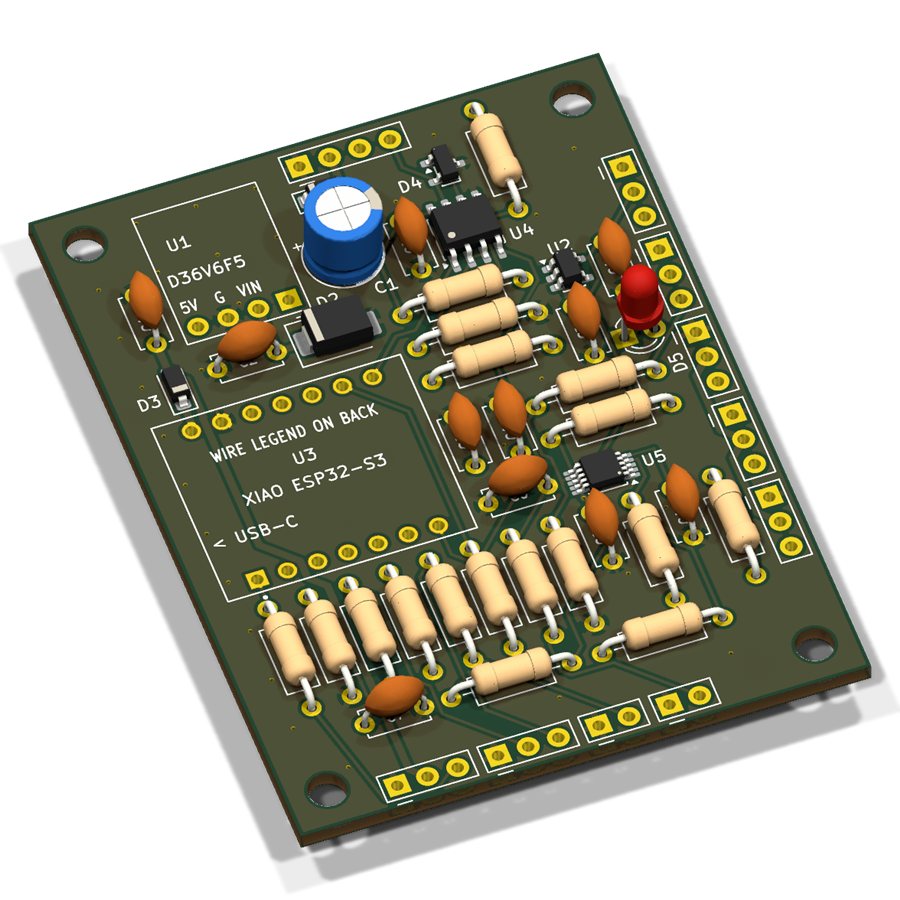
Sensor-pod board, rev B — 48 × 63 mm, 2 layers, on an RS‑485 tether
The pod board carries a Seeed XIAO ESP32-S3 that measures pH, dissolved oxygen, TDS, turbidity and temperature, and the RS-485 tether that talks to it also powers it. A fish-finder sonar replaces the pod’s pressure sensor for depth, and a TCA9548A multiplexer splits one I²C bus into eight sensor channels. Both boards are laid out in KiCad and checked against their schematics.
Two V2 ideas are left out: vision-based obstacle detection, and lowering the pod on a winch for depth profiles. V3 samples at the surface and gets depth from sonar instead. The winch circuit stays on the board for the sample-collection stage that comes later.
V3 stack
Key components & bill of materials
Mission computer · Pi 5
Navigation, mission logic, data logging and the cloud link
Real-time · Teensy 4.1
Sensor I/O, motor commands and safety
Sensor pod · ESP32-S3
pH, DO, TDS, turbidity and temperature at the surface, over an RS-485 tether
Survey loop
Plan a route in the web dashboard, upload it over 4G, drive the waypoints, sample at each station, stream geo-tagged readings to a live map
Raspberry Pi 5navigation · missions · logging · cloud link
Teensy 4.1sensor I/O · motor commands · safety
2× VESC on CAN busdifferential drive · 12S LiPo pack
Seeed XIAO ESP32-S3 pod · RS-485 tetherpH · DO · TDS · turbidity · temp
4G LTEmission upload · live map
SBUS RC receiverhand-held manual override
Carrier rev D (4-layer) + pod board rev Bthree isolated power domains
Modular twin hullin CAD
The V2 software ran against a laptop simulator before any hardware was attached, and its command center still does, in the browser. Its mission was a state machine — transit → deploy → sample → retract → advance — with geo-fenced boundaries and automatic return-to-home on low battery.
V3 is modular by intent: the hull, payload and software are configured for each job, starting with surface water-quality surveys. Swap the pod and the same platform could carry sonar for bathymetric mapping, cameras for an underwater survey, or tools for collecting samples.
Next comes fabricating the boards and assembling the electronics, pod and fish finder into the new hull, then firmware for autonomous waypoint navigation, surface sampling and depth logging, and field trials. We’re talking with the Charles River Watershed Association about collecting water-quality data for them. The CRWA and the Port of Oakland both told us their teams still collect sediment samples by sending divers down, and that is what my robotic arm is for: a deck arm that works with the winch to bring water and sediment samples back.
Project 02 · Competition Robotics
Combat Robotics — Team Dihydrogen Monoxide
CADCNC Machining3D PrintingWeapon Design
Team
Dihydrogen Monoxide
Active
2023 – 2025
Fleet
~10 robots · 5 weight classes
Weapons
Horizontal spinners · vertical drums
Build
In-house 3D print · outsourced CNC
Best result
4th — Nat'l Plastic AW '24
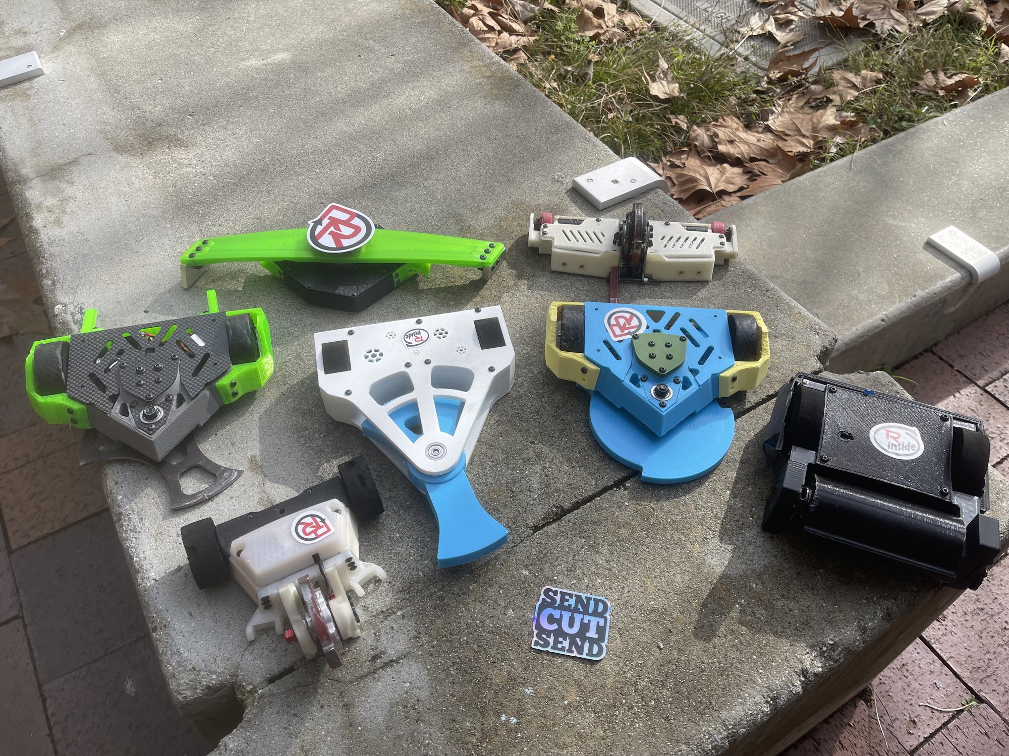
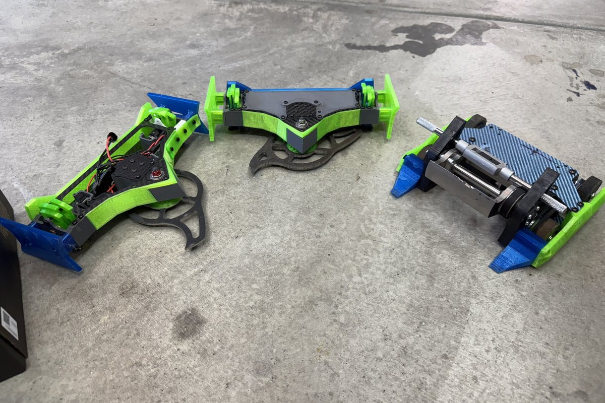
Two years of competitive combat robotics with Team Dihydrogen Monoxide — around ten robots that competed across five weight classes, all designed in CAD and 3D-printed in-house (machining outsourced), and tested by getting hit very hard. The three that ranked nationally are written up below.
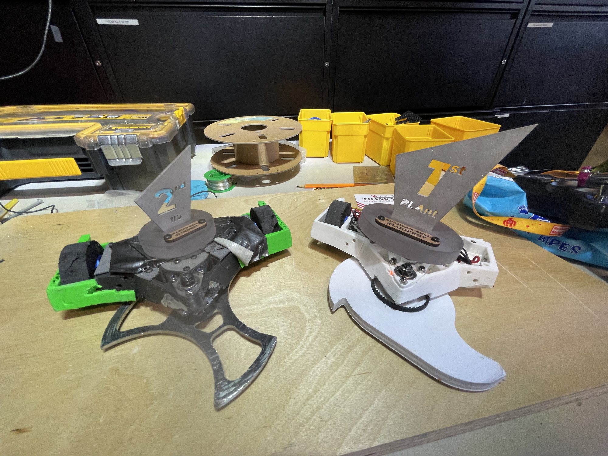
ResultMy own robots took 4 firsts and 8 seconds, and 4th nationally in Plastic Antweight at the 2024 Robot Combat League Championship. As a club, we placed on the podium 16 times across 5 events.
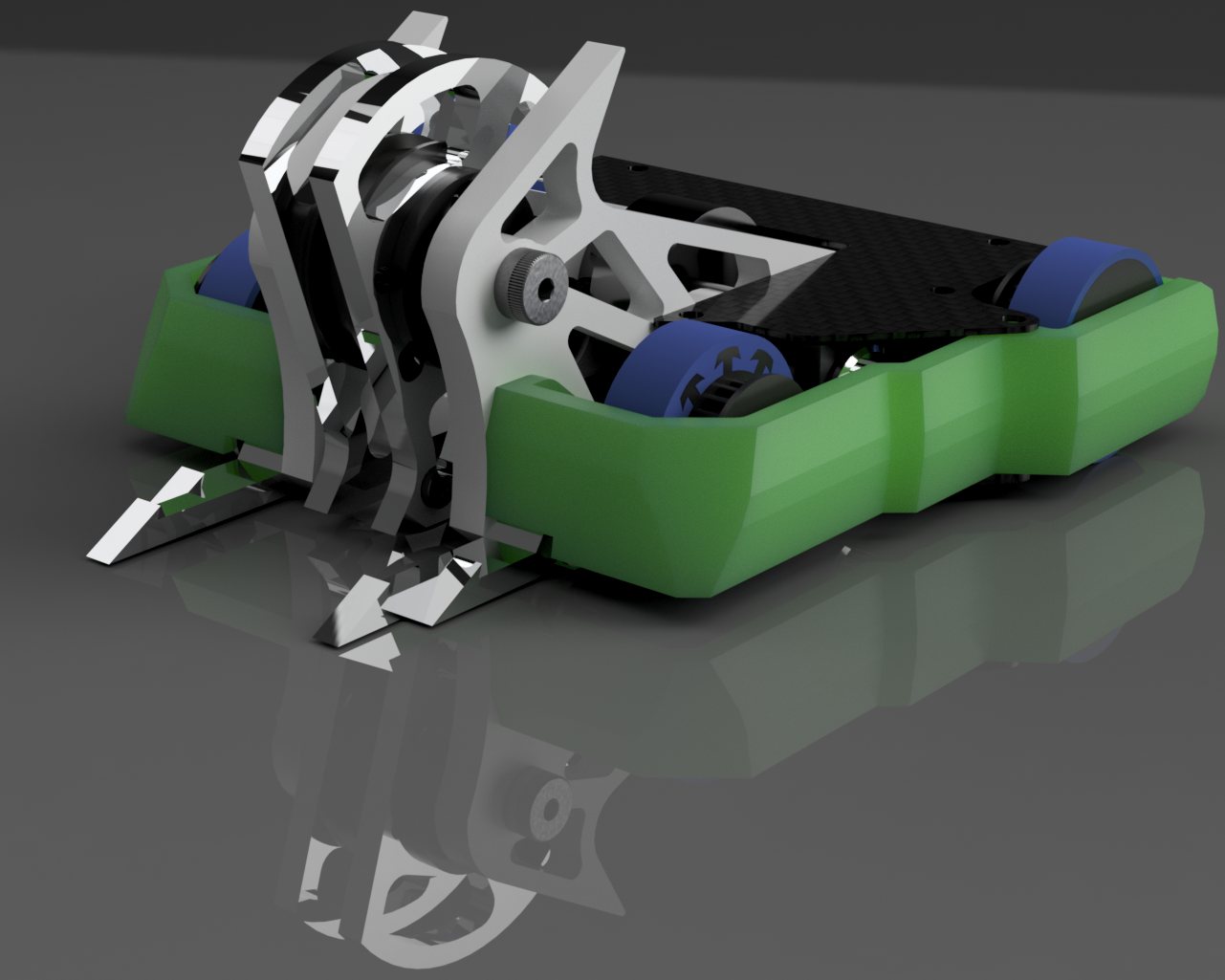
Every robot was designed from scratch in CAD, with weapon systems refined through iterative simulation and real-world testing — horizontal spinners and vertical drums.
We sent the aluminum frames out for CNC machining and printed the armor ourselves, in reinforced nylon and polycarbonate.
Orcus — CAD render
Achilles — a first- and second-place finish in one weekend
The robots
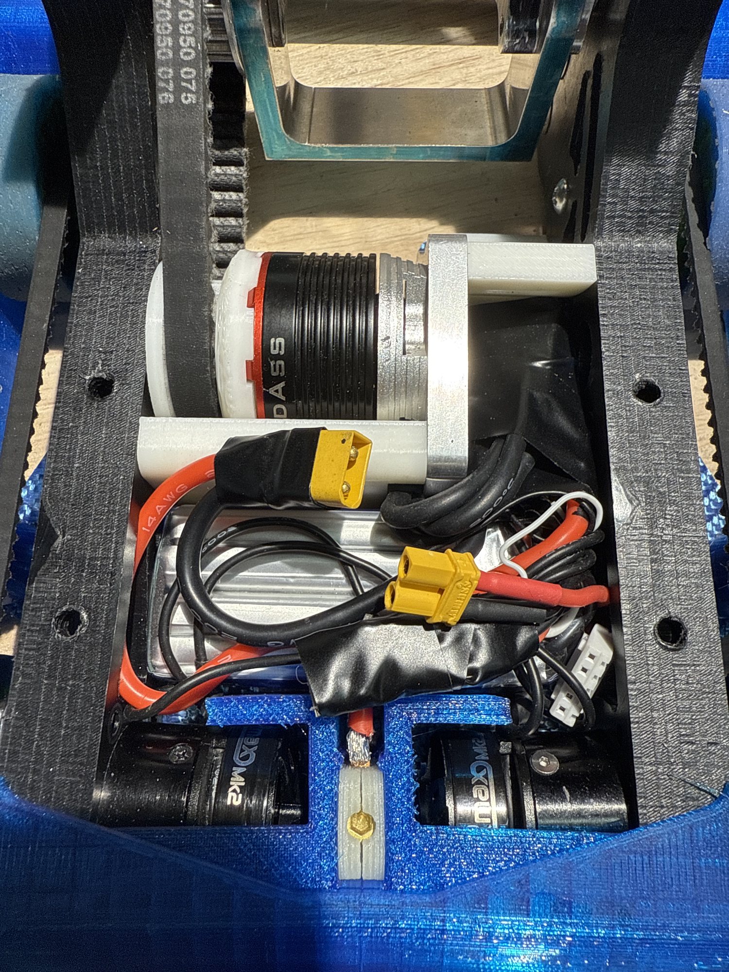
Korybantes v2 — internal layout
Top 35 US · 2025 · 3 lb beater
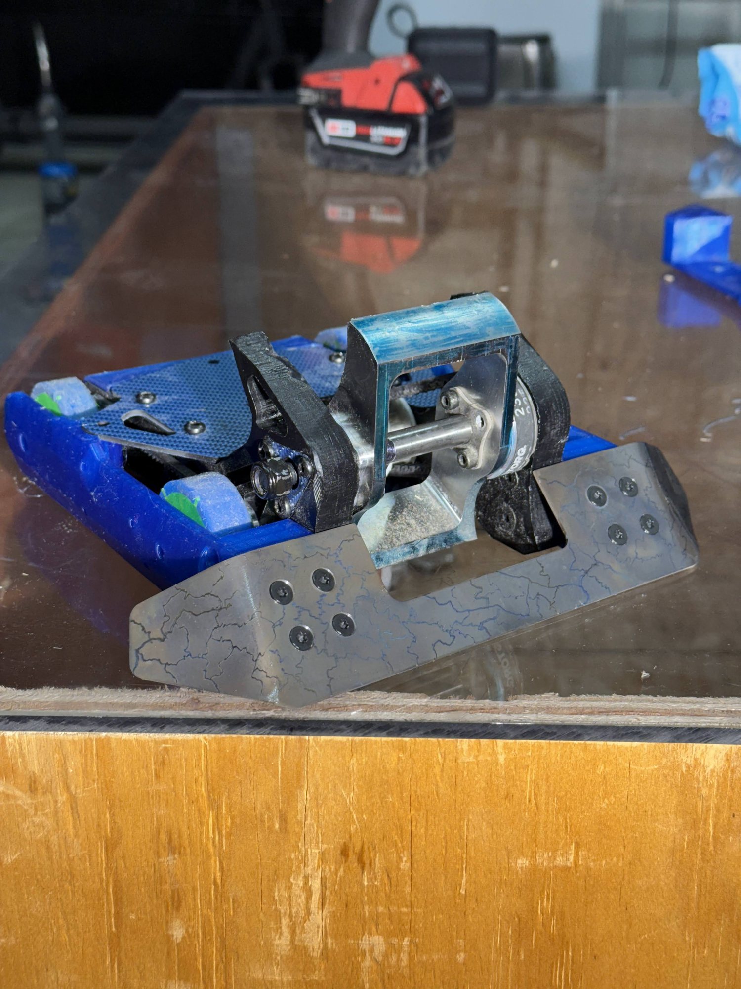
Korybantes — a 3 lb beater built for reliability and fast repair between matches.
6061 aluminum, carbon-fiber plate, laser-cut titanium armor, UHMW impact structures, and in-house 3D-printed assemblies for rapid iteration — the CNC machining and heat-treating were sent out to a shop. The beater delivers consistent kinetic output that holds up under repeated impacts.
Every so often I'd get a design check from senior builders in the community and fold their criticism into the structural reinforcement and drivetrain tuning. Korybantes reached a top-35 U.S. ranking at the 2025 National 3 lb competition.
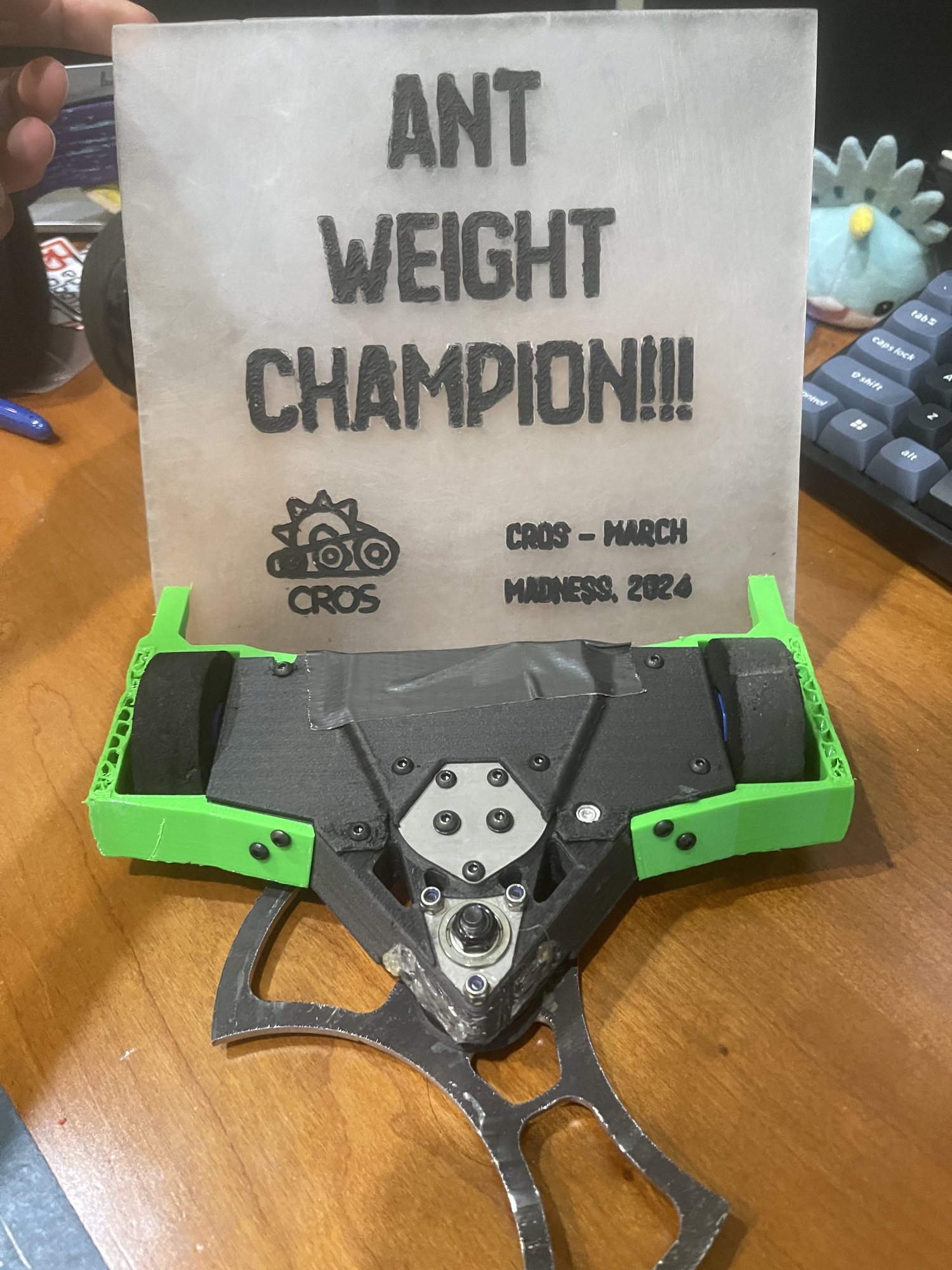
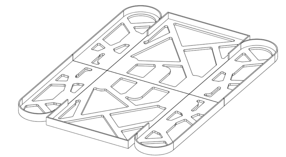
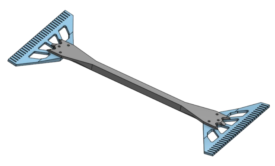
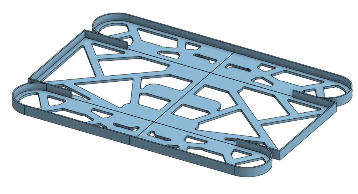
Achilles (metal) — a 1 lb horizontal spinner, the metal evolution of my plastic antweight.
Flexible, modular 3D-printed armor in engineering-grade polymers absorbs impact and swaps fast between matches, while the weapon and structure use AR500 steel and Grade-5 titanium for durability and energy transfer. Every part is designed around real processes — laser cutting, precision machining, and additive-manufacturing tolerances.
Achilles reached a top-15 U.S. ranking and competed at the 2025 National Antweight competition.
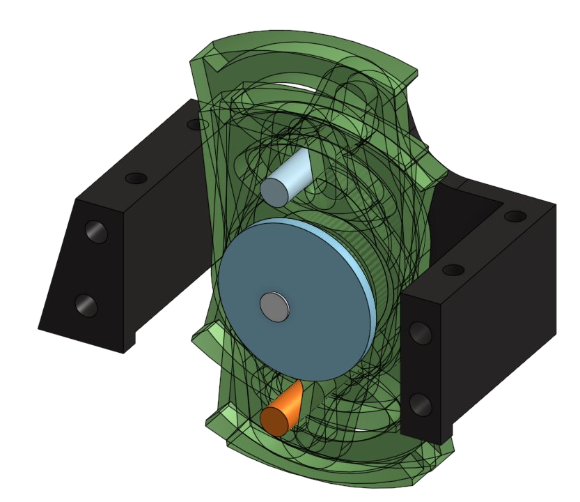
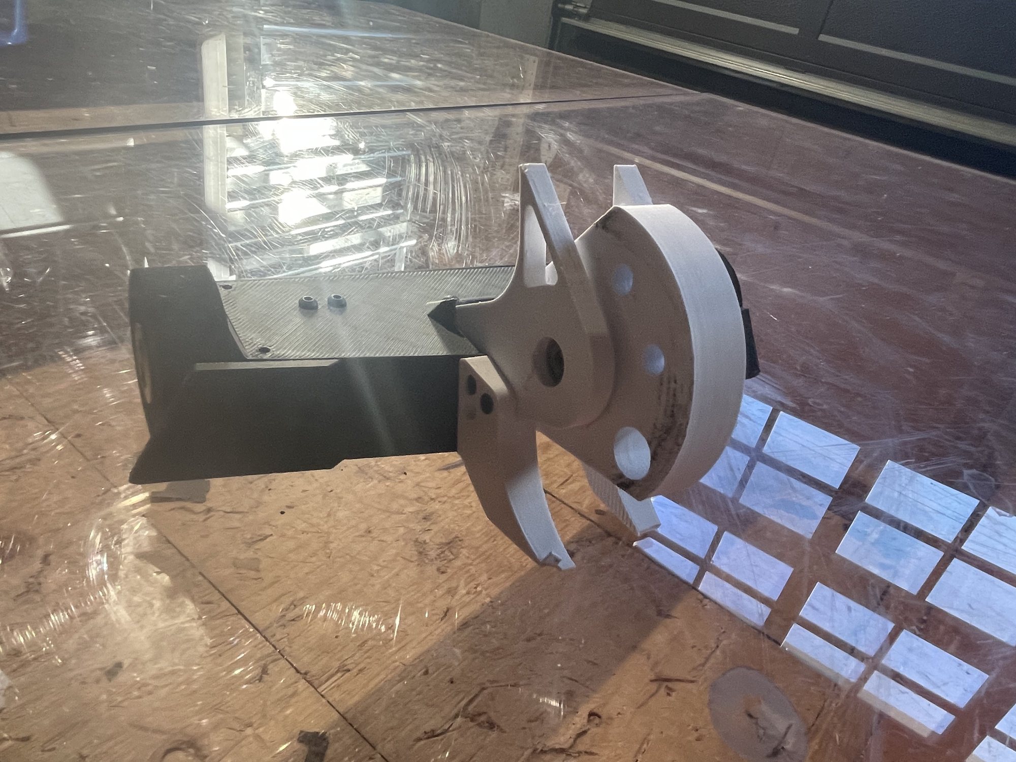
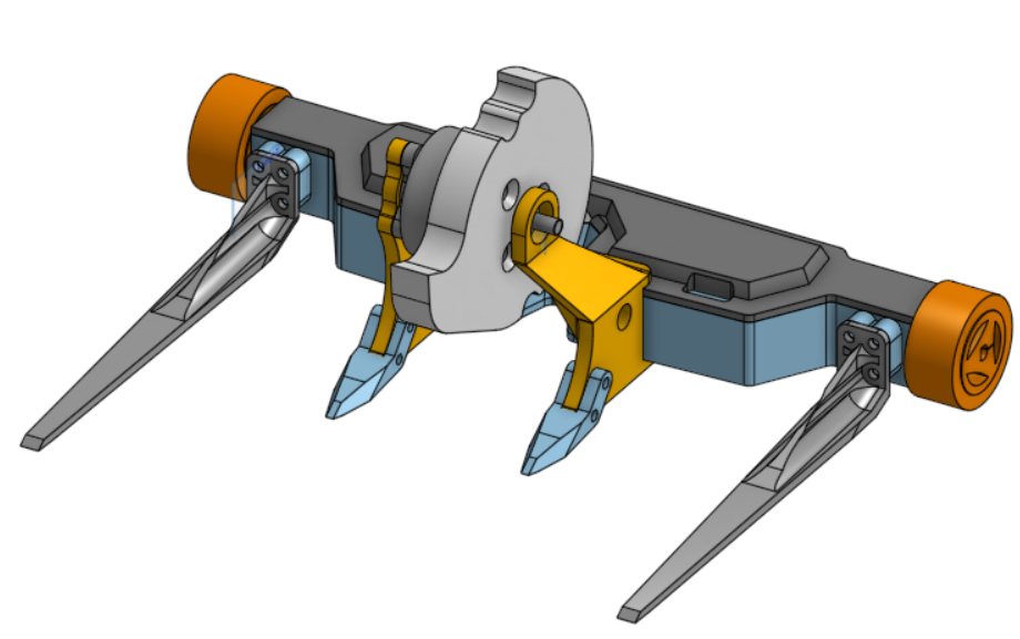
Instead of wheels, the newest version of Achilles walks on a shuffler drive I designed around a single custom cam.
The cam profile drives feet on both the top and the bottom of the chassis, so the robot keeps shuffling forward even after it's flipped — no self-righting mechanism needed, and no dead side to get stuck on mid-match.
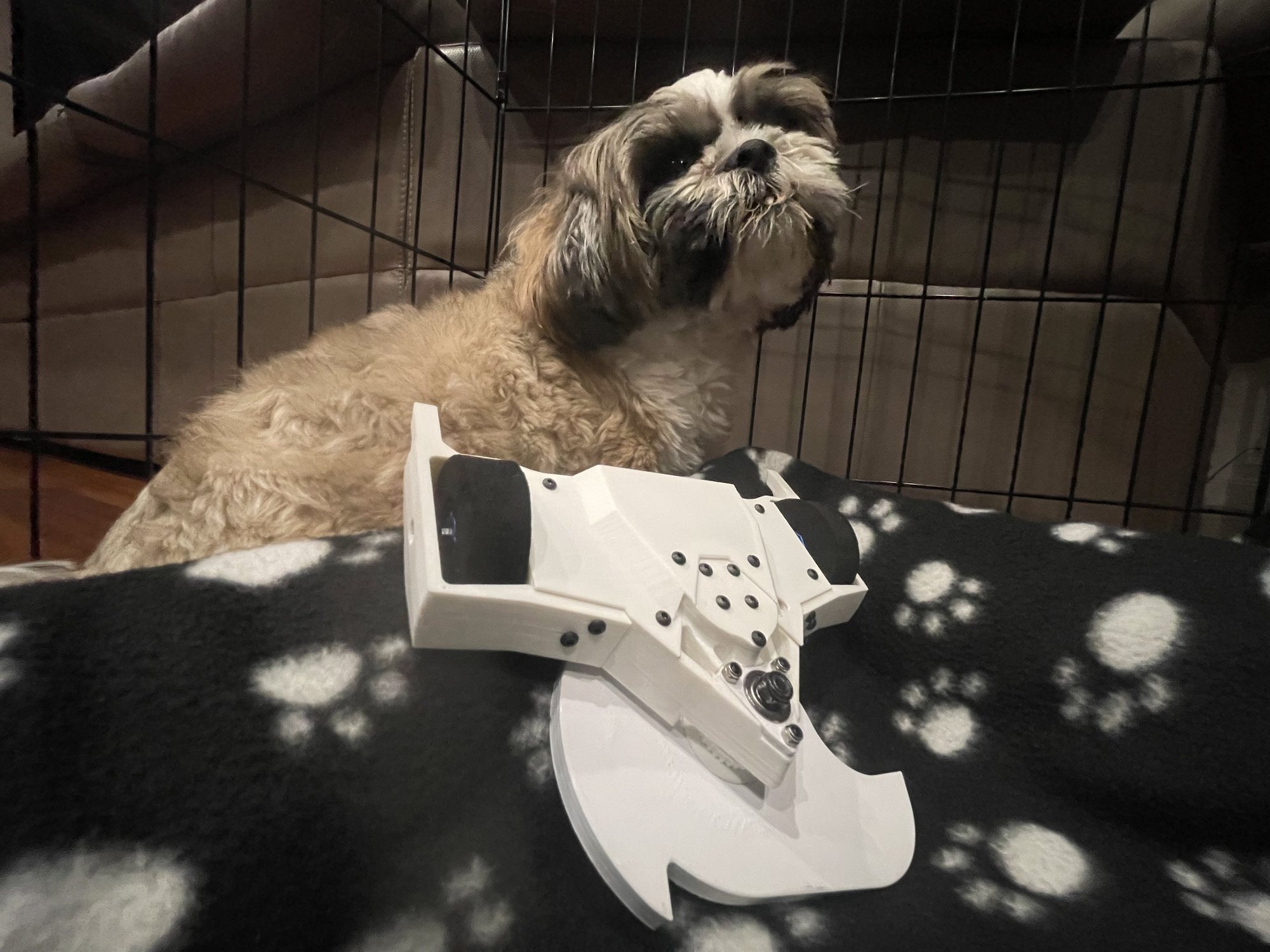
Achilles (plastic), with my dog Mocha
4th National · Top 30 US · 2024 · 1 lb plastic AW
Achilles (plastic) — the 1 lb belt-driven undercutter that started it all.
Designed in CAD and printed, with a modular plastic chassis for fast, reliable repairs. I handled the CAD, soldering, and wiring, tuning the weight distribution to manage the spinner's gyroscopic forces.
It placed 4th at a national plastic-antweight competition and ranked among the top 30 in the U.S. (2024). It also helped shape the low-profile, belt-driven undercutter meta in the Northern California scene.
More of the roster
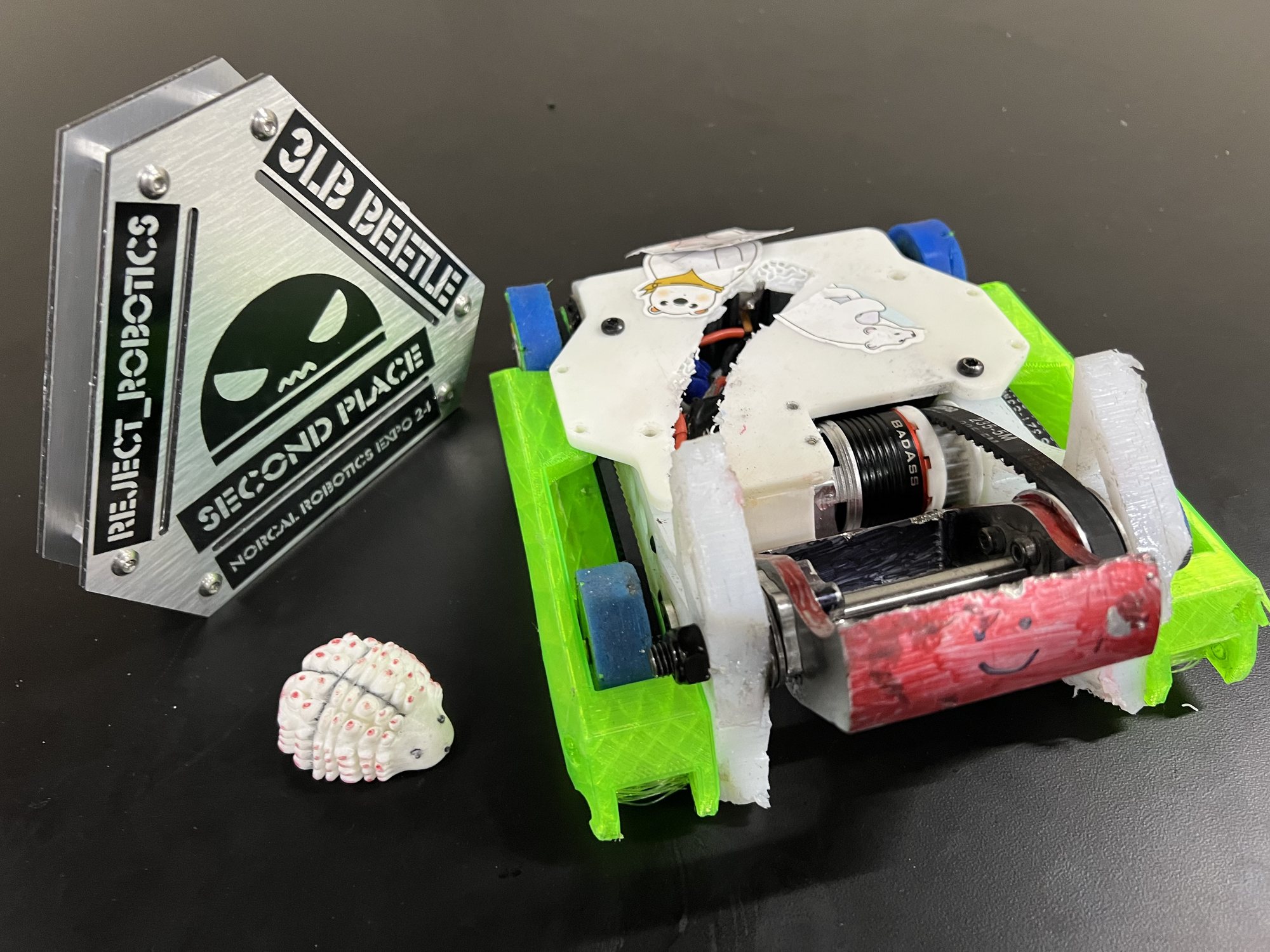
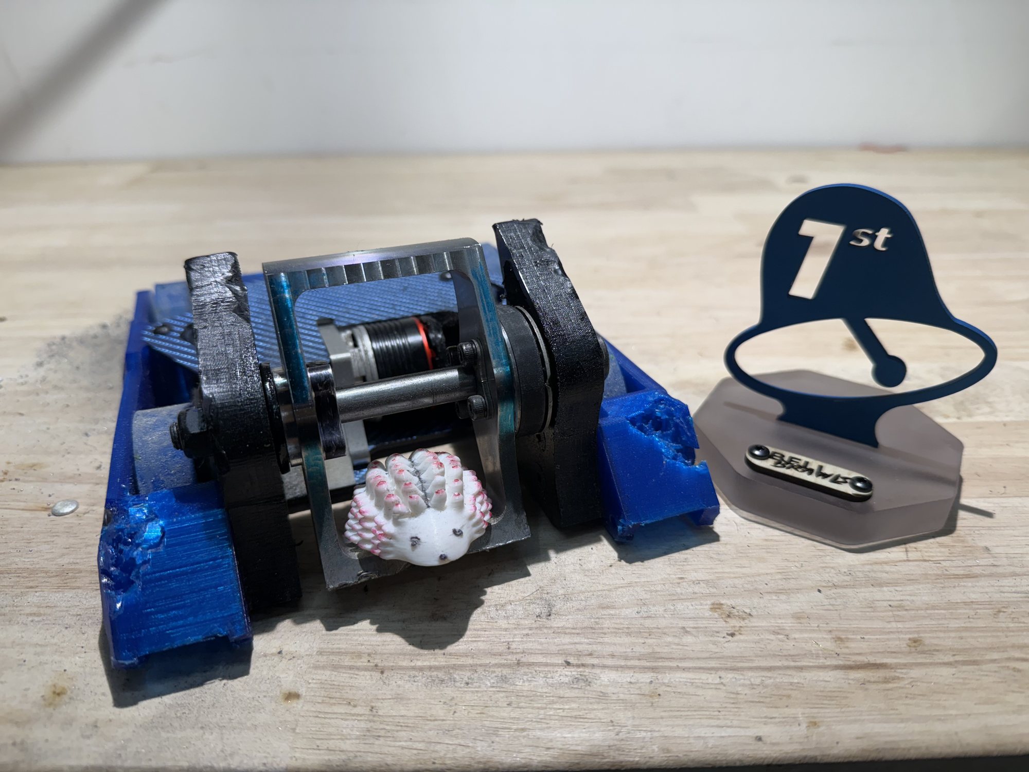
Korybantes v1, with trophyKorybantes v2Korybantes v2, with trophyArtemisiaSqueak
After every match, win or lose, we'd pull the robot apart and work out what broke and why — every design generation came straight out of that damage analysis, so I learned to design for repairability first.
The best part was teaching. As club president I ran workshops on CAD, soldering, physics, and fabrication. A few members went on to build and compete with robots of their own.
Project 04 · Mechatronics & Firmware
Autonomous Maze-Navigating Robot
Onshape3D PrintingMicroPythonasyncioProportional Control
Course
Cornerstone of Eng. · NU
Team
With Matthew Hong · my CAD, prints + code
Control
1× RPi Pico · MicroPython · asyncio
Sensing
2× angled ultrasonic · front IR
Drive
Tank drive · 2 geared DC motors
Steering
Proportional wall-centering
A tank-drive robot that steers itself through a maze, built with Matthew Hong for Northeastern's Cornerstone of Engineering course. I designed it in Onshape, printed every part, and wrote the MicroPython firmware; Matthew designed and printed the wall brackets, built the maze we set for another team, and helped with the wiring.
ResultCompleted all three challenges: a straight run, a preset path of timed turns, and a maze it steered through on its own, off two angled ultrasonic sensors.
Every team started from the same base kit and had the same brief: get a robot through three courses of varying difficulty, then build a maze for another team to run.
The kit sat tall and tipped in fast or sharp turns, its ping-pong-ball caster steered inconsistently, and it had nowhere to mount extra parts. Rather than fix those one at a time, I designed a new robot around them.
Our robot in front of the class kit it replaced
Problem
Class kit
Our robot
Steering
A ping-pong-ball caster that steered inconsistently
Tank drive: turns in place
Stability
Tall enough to tip in fast turns
1.6 in without the LCD, about half the kit
Mounting
Nowhere to mount extra parts
A mount for every board and sensor
Sketch to CAD
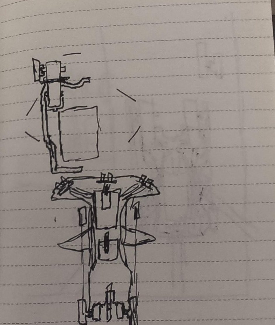
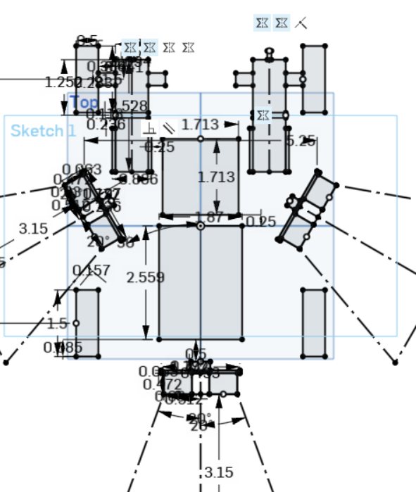
I started on paper, sketching chassis shapes, sensor placements and drivetrains, then drew the layout that worked as a master sketch in Onshape and modeled every part off it. Checking each dimension and constraint in CAD before exporting meant every printed part fit on the first print.
Notebook sketch: chassis layout and sensor placementThe Onshape master sketch the parts were modeled from, sensor cones drawn in
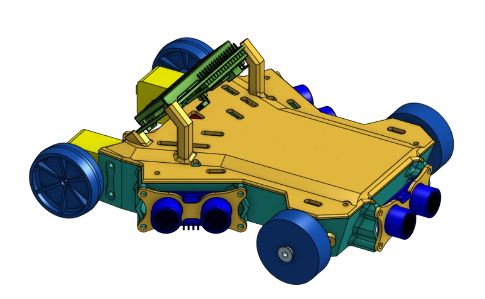
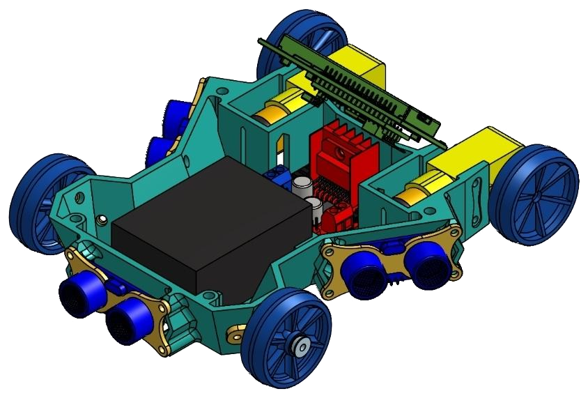
The finished model, top plate onTop plate off: the battery pack and motor driver sit inside the body
We ranked what mattered: control in slow turns, accurate sensor readings, quick switching between programs, and clean wiring.
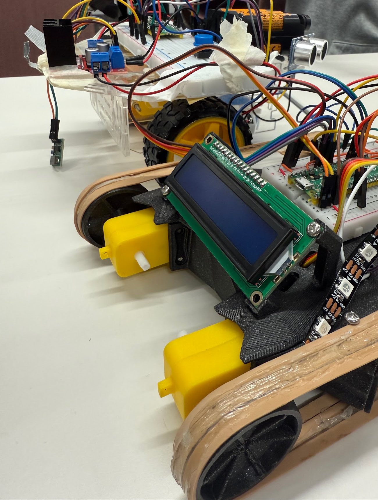
Two geared DC motors each drive a rubber-band tread around a dead wheel, one motor per side. The battery and motor driver sit inside the body, which keeps the weight low and protects them; the Pico and breadboard stay on top, where uploading code and troubleshooting are easy.
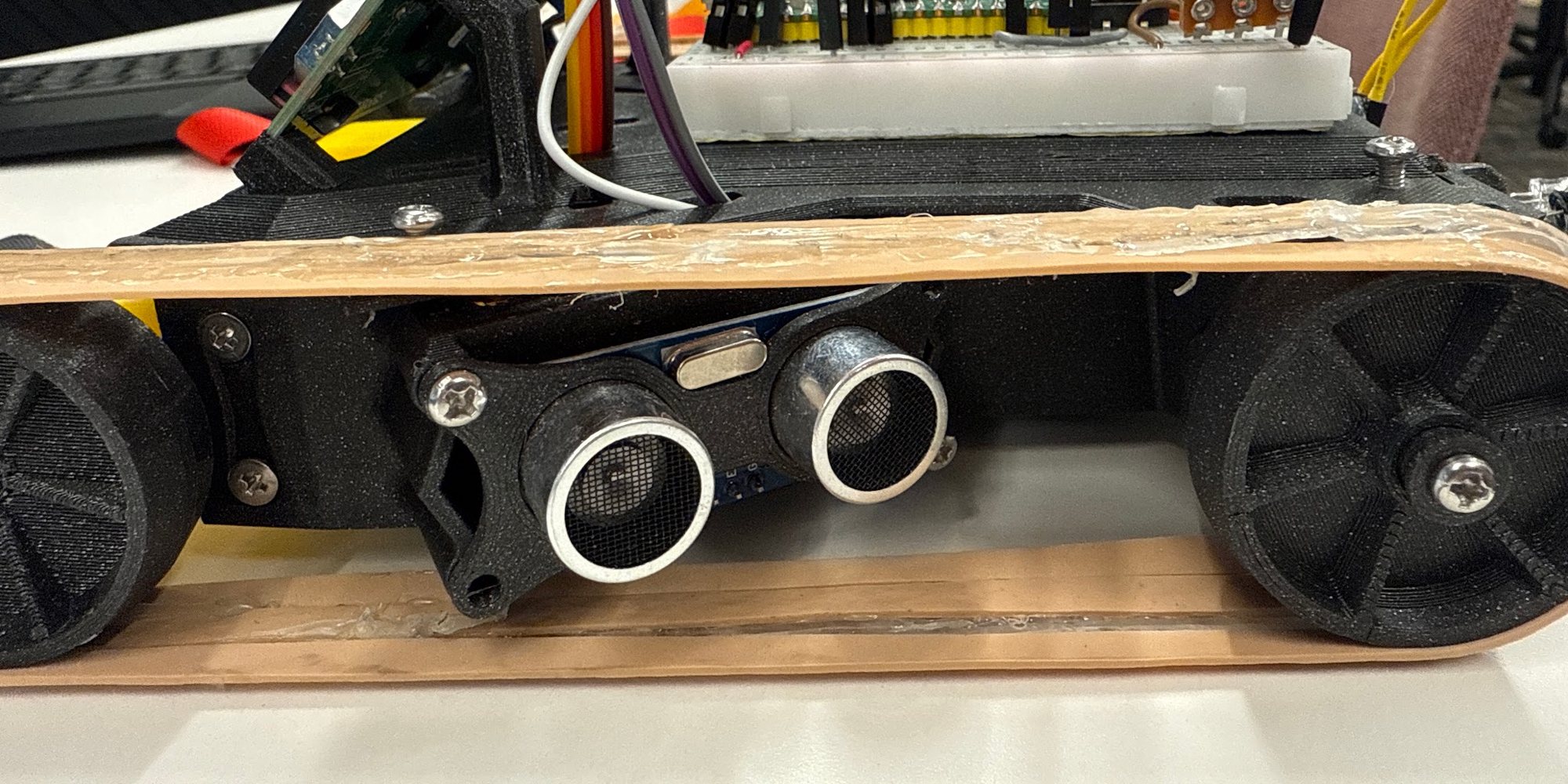
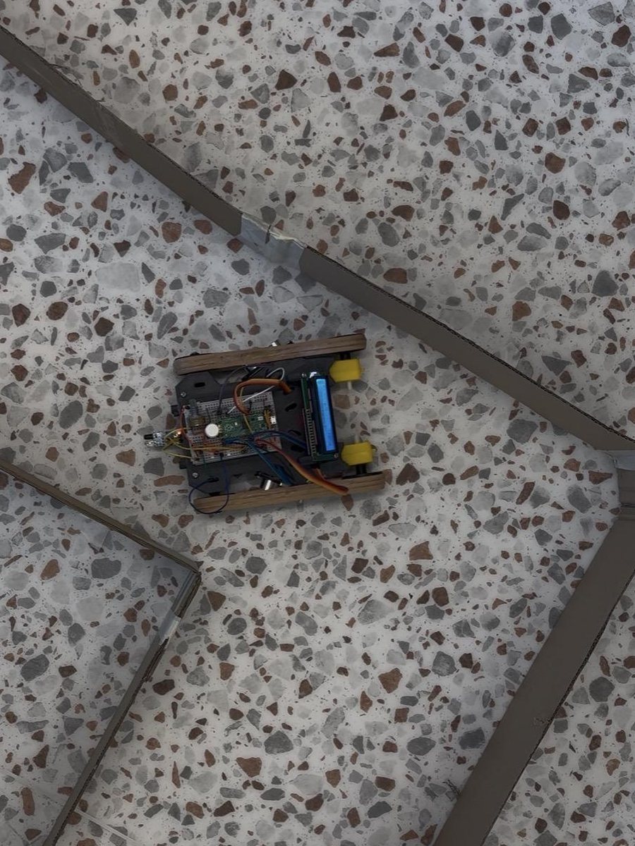
The two ultrasonic sensors angle outward to spot turns early, and sit recessed between the treads, so a scrape along a wall hits the tread instead of the sensor.
What broke, and what changed
Most of the design came out of testing. Matthew and I took turns: one of us ran the robot through the course while the other watched for what went wrong.
FIX 01 — TREADS
Treads that stay on
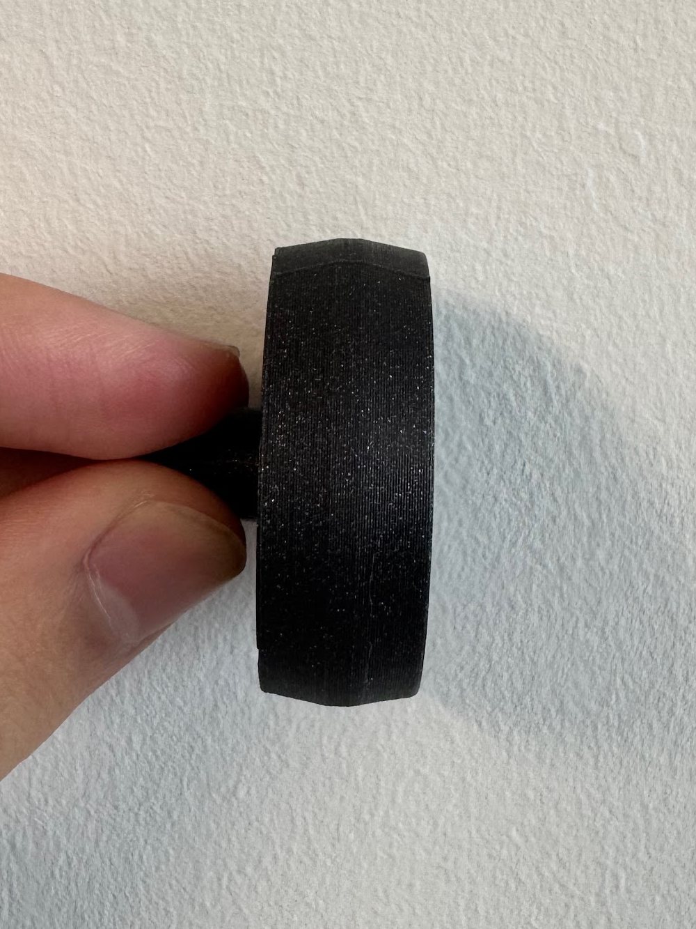
The treads are rubber bands, and in hard turns they walked off the wheels. Belt drives solve the same problem with crowned pulleys, which keep a belt centered on their own, so I reprinted the wheels with a convex face that brings the band back to the middle as they turn.
A tread off its wheels after a hard turnThe reprinted wheel, edge-on: the convex face keeps the band centered
FIX 02 — WALLS AHEAD
A wall it couldn’t see
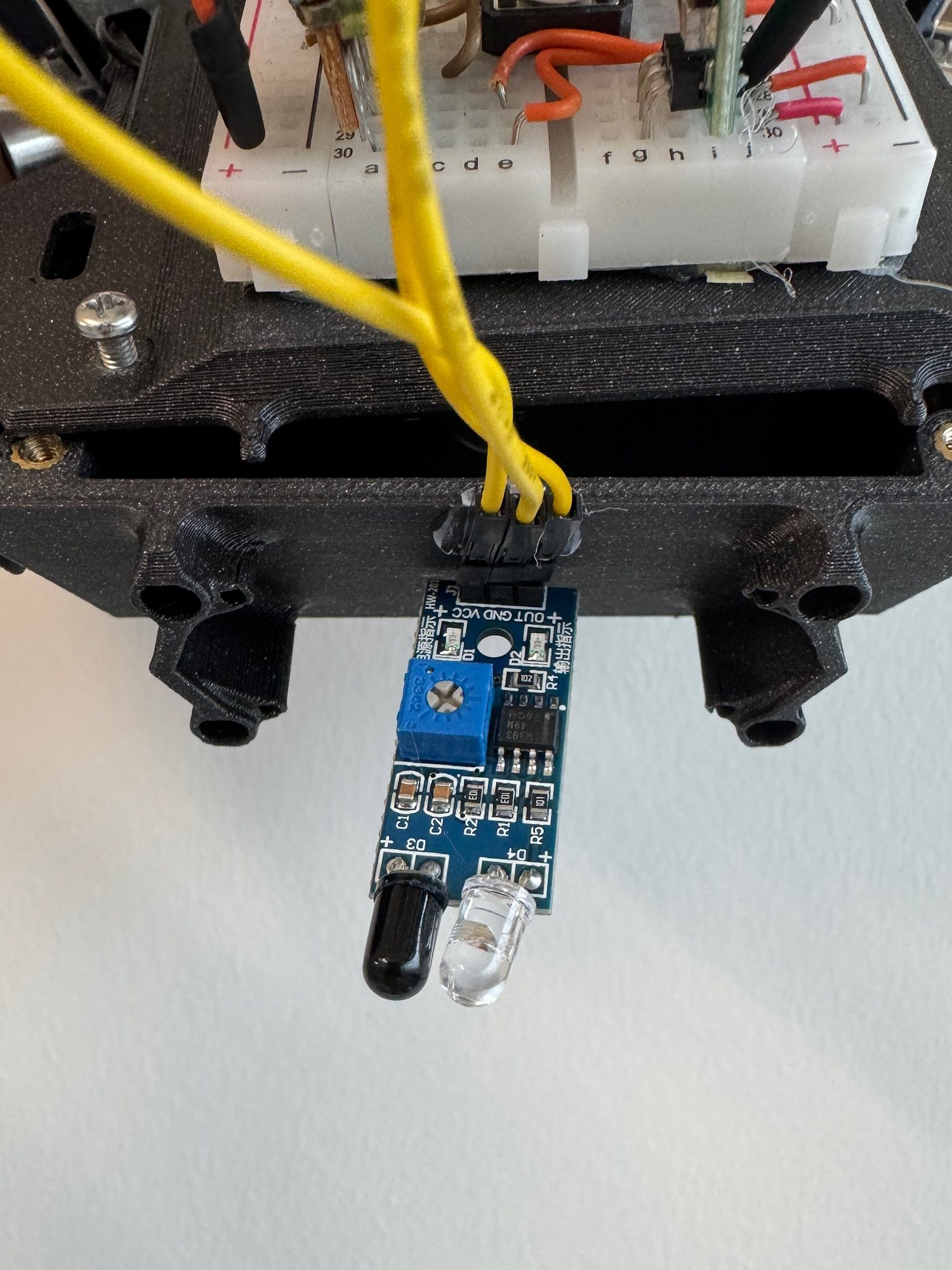
With both ultrasonic sensors angled out to the sides, nothing looked straight ahead, and the robot ran into walls. I added an infrared sensor at the front to detect walls straight ahead.
Nose-first into a maze wallThe IR sensor added at the front
FIX 03 — TUNING
Finding the gain
Tuning the steering took a lot of testing. Too much correction and the robot jittered and overcorrected; too little and tight turns got harder. We tried a function for pre-set turns, which needed precise sensor readings, and slowing the motors through turns, before finding that the real problem was traction.
Carpet was harder still: its higher friction made the treads grip unevenly, and the robot struggled to turn. We didn’t fix that during testing; turning in place on the tank drive could solve it.
Overcorrecting at a corner
FIX 04 — PROGRAMS
One robot, three programs
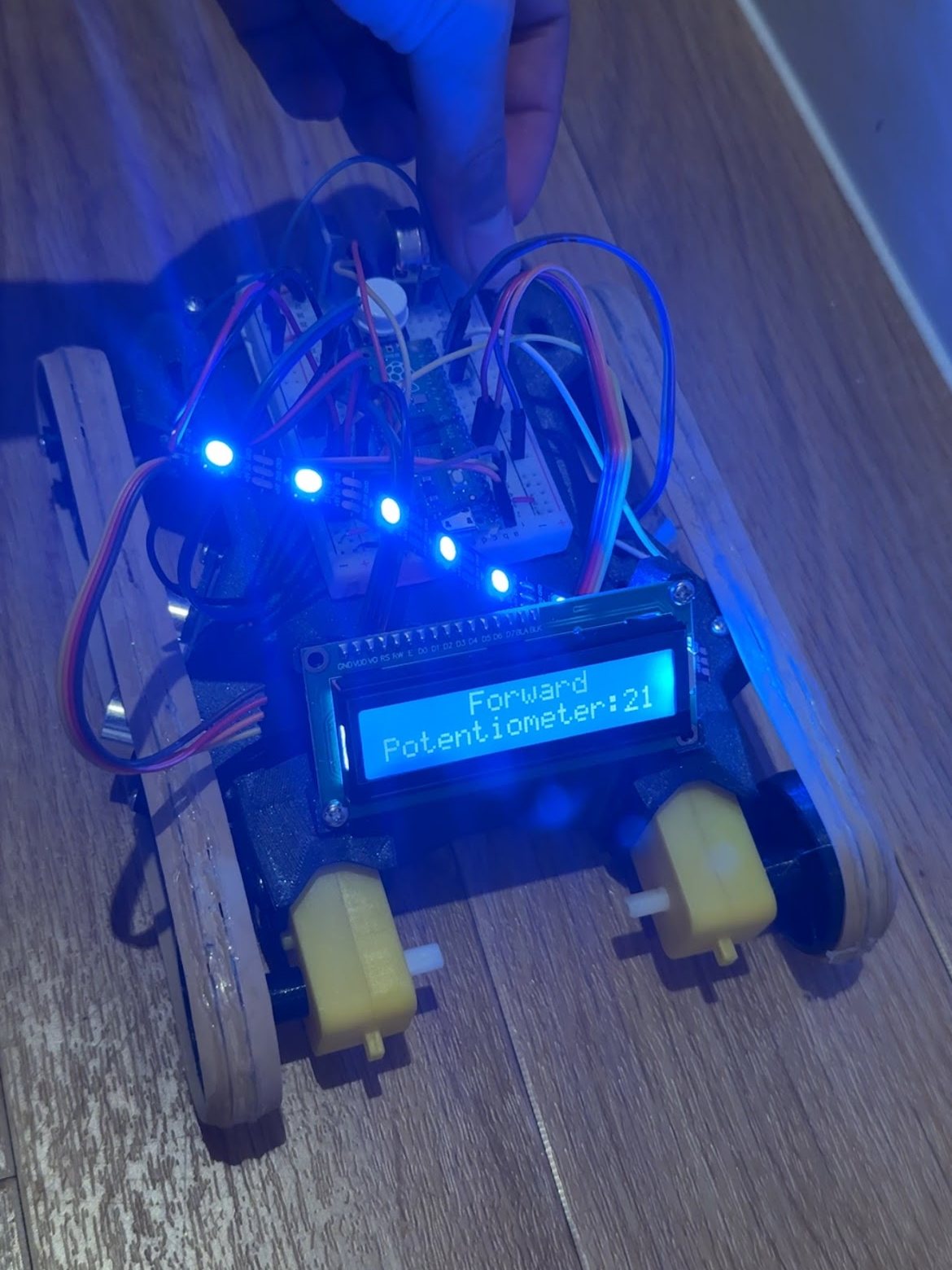
Switching between the three challenge programs meant uploading new code over USB every time. I wired a potentiometer and a button to the Pico: turning the knob pages through Forward, Preset Path and Maze on the LCD, and a press starts the run. For problems the LCD couldn’t show, print statements reported sensor readings and variable states in real time.
FIX 05 — FREEZES
Animations that froze the motors
The LED and LCD animations blocked motor control and froze the robot. After many failed attempts at interleaving them by hand, I restructured the modules around MicroPython’s asyncio, so the animations run as their own tasks alongside the steering loop.
The knob menu: “Forward” selected, the knob’s reading underneath
Firmware
The maze program is a proportional controller. Each pass it compares the two side distances and steers by the difference: drift toward the left wall and the left tread speeds up while the right slows, turning the robot back toward the middle.
The gain sets how hard it corrects, and a clamp holds both motors between 20 and 100% duty so neither runs too fast or too slow. In the final code that’s a 55% base speed and a gain of 4.
The sensors, knob, button, LEDs, LCD and motors each have their own module, and main.py ties them together.
Knob menu on the LCD; the button starts the chosen run
Task · steer
Proportional wall-centering, the timed preset path, 1 kHz PWM drive
Task · sense
Two ultrasonic ranges in cm (30 ms echo timeout) · front IR
Task · show
NeoPixel animations and 16×2 I2C LCD text, each its own asyncio task
What I’d carry forward: prototype early, before committing to prints; structure code as modules from the start instead of untangling it later; and design for the person testing it, even on a prototype. The LCD menu made every test run faster.
That same asyncio architecture carried straight into the survey boat's firmware — concurrent tasks on one Pico, just on water instead of in a maze.
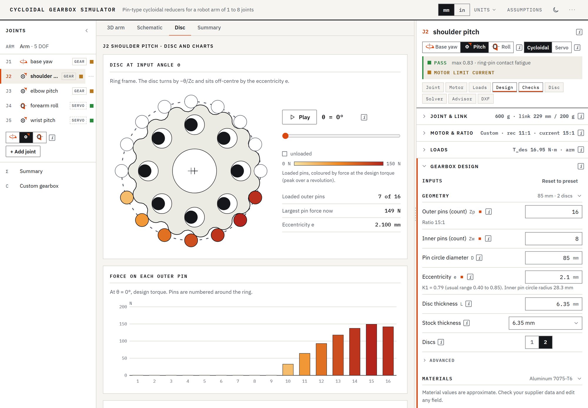
A five-axis arm with a compliant TPU gripper that reads its own grip force. The base, shoulder and elbow run cycloidal gearboxes with a magnetic encoder on the output shaft rather than the motor, which is what makes a ±0.25° static target worth aiming at. Forearm roll and the wrist are direct-drive servos with encoders of their own.
StatusNothing is built yet. Joint layout, link lengths, gear ratios, ring sizes, materials, bearings and the manufacturing route are set, and all three gearboxes pass every check in the simulator I built for them; real masses from CAD are not in yet. The first prototype gets printed to check motion and tune the loop — the ±0.25° figure is for the aluminum version, because printed cycloidal backlash will exceed it on its own.
Joint layout, schematic and not to scale. The circles are the three pitch joints that hold gravity; J1 yaws on its thrust bearing and J4 rolls about the forearm.
Five joints: base yaw, shoulder pitch, elbow pitch, forearm roll, wrist pitch. Three of them hold gravity, and the shoulder holds everything past it at the longest lever arm, so that is where the torque capacity goes.
A sixth joint — gripper swivel — got cut as redundant with forearm roll. The cost is that roll sits before the wrist, so changing it also rotates the plane the wrist bends in. For pick-and-place with a symmetric two-jaw gripper that does not matter.
Joint
Holds gravity
Actuator
J1 · base yaw
No — the thrust bearing carries it
NEMA 17 · 14:1 · 80 mm ring, printed PLA
J2 · shoulder
Yes — longest lever arm
NEMA 23 · 15:1 · 85 mm ring
J3 · elbow
Yes — shorter lever arm
NEMA 17 · 22:1 · 51 mm ring
J4 · forearm roll
Only with the wrist bent — the payload then sits off its axis
2.5 N·m servo with encoder, direct drive
J5 · wrist
Yes — smallest lever arm
2.5 N·m servo with encoder, direct drive
Every joint is sized for its worst pose: the arm straight out with a 1.2 kg payload at the tip, accelerating at 3 rad/s². That puts the shoulder at 11.30 N·m and the elbow at 4.70 N·m, and a 1.5 service factor makes them 16.95 and 7.05 N·m to design for. The shoulder’s NEMA 23, at 1.9 N·m, gives about 24 N·m through 15:1 at 85% efficiency, the elbow’s NEMA 17 about 8.4 N·m through 22:1, and each servo needs 0.96 N·m of its 2.5. The joint and link masses behind those numbers are estimates rather than CAD figures, and wiring and fasteners always come in heavier than expected.
Why the rings are different sizes
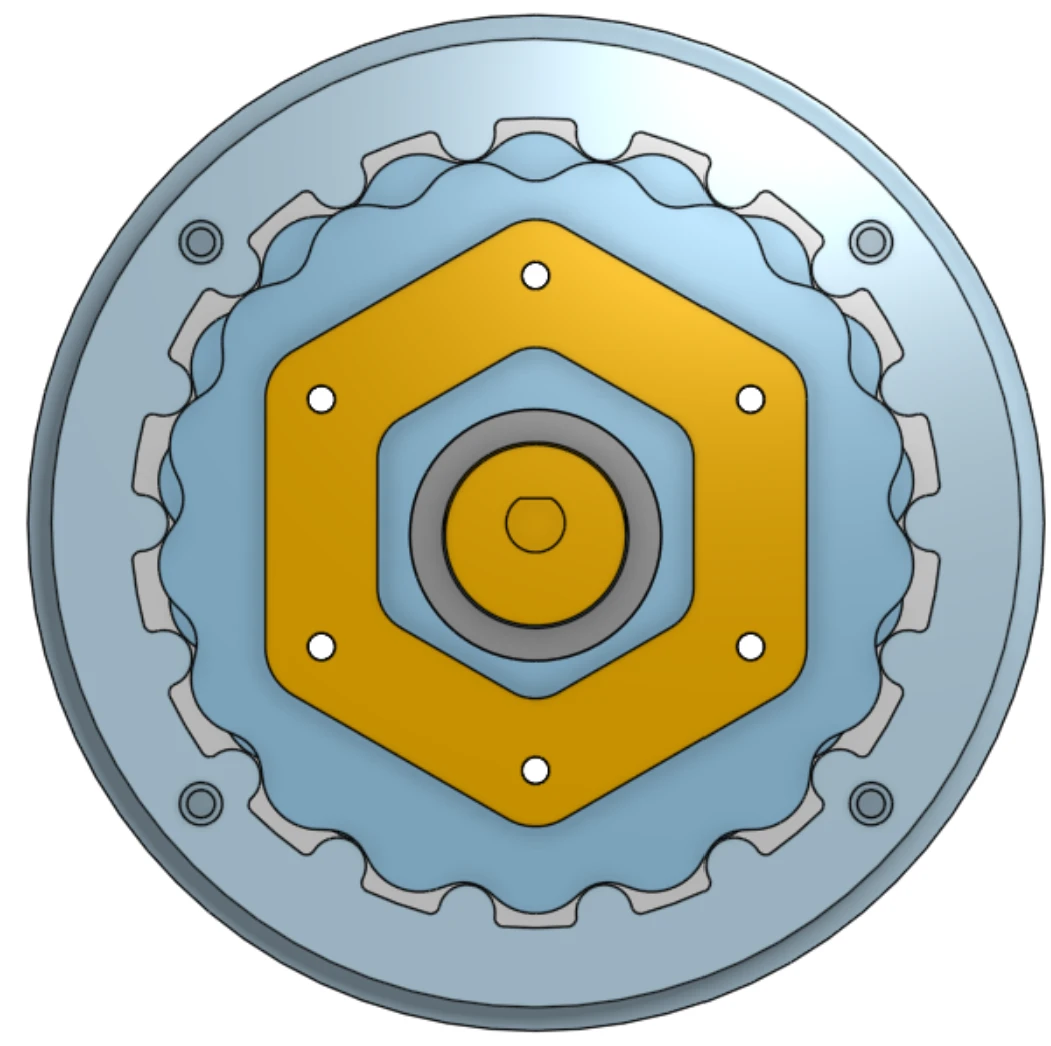
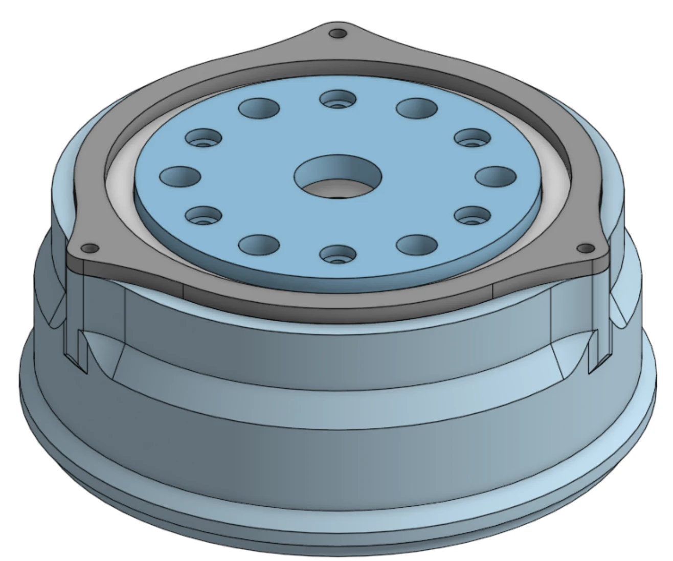
Axial view — the lobe profile inside the pinned ring, hex output carrier at the centerThe same joint assembled — output flange bolt circle and retaining plate
One gearbox part for all three geared joints would have been the easy call. It is the wrong one. Pin contact stress scales roughly as (1/scale)1.5, so a smaller ring pays for its size in stress: in the simulator the elbow’s 51 mm ring reaches the same peak contact stress as the shoulder’s 85 mm one, about 470 MPa, at well under half the torque. Worse, a fixed manufacturing tolerance becomes a larger angular error at a smaller radius, because the error divides by the radius — shrinking the gear works against the tolerance target, not toward it.
So each ring is sized to its own joint. J2 kept all 85 mm, with two 7075-T6 discs. J3 carries well under half the shoulder’s torque, so it dropped to 51 mm and runs 22:1, enough for a NEMA 17 to drive it. J1 carries inertia alone, light enough for plastic. For now its 80 mm discs and housing are printed in PLA, with the outer pins printed as part of the housing, because it is a large part and aluminum would cost more; it may move to aluminum later. J4 lost its gearbox; it and the wrist are now direct-drive servos.
The aluminum gearboxes share one build. Steel outer pins are pressed into the housing, and the output pins are standoffs. I’ll machine the housings myself on a Tormach mill, which I’m learning this fall. SendCutSend laser-cuts the 7075 discs, and I finish them on a Bantam desktop PCB mill for accuracy; the tolerance budget below is why that pass exists.
The housing has room to lose too. The input shaft is 20 mm because of 3D printing, where a torsion check puts the real minimum under 4 mm; at 8–10 mm it keeps a wide margin and drops to a far cheaper bearing, taking the shell from about 127 mm toward 100 mm.
The simulator that checks them
I built a browser tool to size these gearboxes, the Cycloidal Gearbox Simulator. It takes the arm joint by joint (masses, link lengths, the payload), works out what each joint carries in its worst pose, and checks each gearbox against the ways it can fail: contact stress at the ring pins and output holes, for yield and for fatigue; pin and standoff bending; the ligaments between holes; undercut in the lobe profile; and the eccentric bearing’s static load and rated life.
A check passes below 0.85 of its limit. The torques, ratios and ring sizes on this page come from one saved session, and all three gearboxes pass.
The simulator on the shoulder joint — 7 of its 16 ring pins carry load at this input angle, coloured by force at the design torque
Joint
Design torque
Tightest check, share of its limit
J1 · base · 14:1
2.00 N·m
0.66 · ring contact fatigue, in PLA
J2 · shoulder · 15:1
16.95 N·m
0.83 · ring contact fatigue
J3 · elbow · 22:1
7.05 N·m
0.84 · ring contact fatigue
J4, J5 · servos
1.43 N·m
0.57 · servo torque, 2.5 N·m rated
The tightest bearing check is the shoulder’s rated life: 2,522 h against a 2,000 h target for its 6704. The motors get checked through their gearboxes too. Every ratio here is above the minimum its motor needs, so a stalled motor could push its gearbox past the design torque; the simulator turns that into a driver current limit for each joint, about 37% of peak current at the base, 70% at the shoulder and 84% at the elbow.
SoftwareThe simulator was built with AI coding agents. I specified what it models and checks — the arm load model, each failure check and its limit, and the validation cases its test suite has to match — and the agents wrote the code.
The discs start as laser-cut blanks from SendCutSend, and a finishing pass on a Bantam desktop PCB mill, which I run, sets their final accuracy. At the 85 mm ring’s 42.5 mm radius a linear profile error becomes an angular one, and the budget is small enough that the finished profile, not the cut, decides the answer.
Profile error
Angular error
Share of the budget
±0.05 mm
±0.067°
~27%
±0.10 mm
±0.135°
~54%
±0.15 mm
±0.20°
~80%
At ±0.05 mm there is room left for backlash and structural compliance, which are the larger errors anyway. At ±0.15 mm four fifths of the budget is gone to one source before the arm has moved. That is why the discs get a finishing pass: the laser gets them close, and the mill takes the profile the rest of the way, cleaning up the cut edge exactly where the rolling contact happens.
Picking the feedback, and what got rejected
The encoder sits on the gearbox output, not the motor. It reads the joint angle directly, so the gear ratio drops out of the precision question and only affects torque and speed. It is a 12-bit AS5600 at 0.09° per count, about 2.8× under the target — thin, but backlash and compliance are the bigger errors at this tolerance, so a 14-bit part would be buying precision in the wrong place.
An IMU was the other candidate and does not work here. An IMU measures a link’s orientation against gravity, so it is blind to rotation about a vertical axis — that alone rules out base yaw without leaning on a magnetometer. Even with good fusion an IMU holds roughly 1–3° statically, against a ±0.25° target. It may come back as a supplement on the end effector for an absolute level reference or vibration sensing, but not as the joint sensor.
Forearm roll has a wiring problem rather than a sensing one. The wire sits untwisted at encoder center and a single hard stop sits directly opposite, so the joint swings freely between but never accumulates past a half turn of twist. That stop is physical as well as in firmware — a software limit alone does not protect the wire if the encoder glitches or the board loses position across a power cycle.
The gripper
Load path
Object
Rigid fingertip pad
Load cell
Stiff finger base
The TPU flexure bends beside this path, not in it.
Closing
Position control
Cells hit target force
Hold
How grip force reaches the sensor, and how a grasp closes
Two TPU flexure fingers driven by one servo through a 1:1 gear mesh, so both sides mirror each other. The compliance does the accommodating; a load cell per side does the measuring.
The part that matters is the load path. The fingertip pad is rigid, the load cell sits behind it, and it anchors to the stiff base of the finger, so force reaches the sensor without passing through the flexing TPU. The finger still conforms to the object and the reading is not corrupted by the finger’s own bending. Closing is position control until the cells hit the target force, then hold.
Still open here: TPU shore hardness, and print orientation at the flexure so the bend point does not delaminate over cycles.
Where the boat comes in
Further out, this is the deck arm for the survey boat, working with its winch to bring water and sediment samples back. Our conversations with the Port of Oakland and the Charles River Watershed Association showed that their teams still collect sediment by sending divers down. A submersible on the tether collects the sample; the arm takes the full container off it, stores it aboard, and puts an empty collector back. That is the reason for grip-force feedback and a compliant gripper rather than a rigid claw — a tethered submersible under a moving boat will not present itself at a repeatable position.
The interface between the two is not defined yet, and the marine side is deliberately deferred: sealed encoder housings, waterproof connectors, marine-rated bearings, anodised rather than bare 6061. None of that gets designed until the mechanism works on a bench.
Still open before hardware: the tolerance the finished discs actually hold, whether J1 moves from printed PLA to aluminum, and real link masses from CAD to replace the estimates above.
Project 05 · Assorted
Miscellaneous Builds
Smaller builds that don't need a page of their own. Repairs, one-offs, and a few things I made just to learn how.
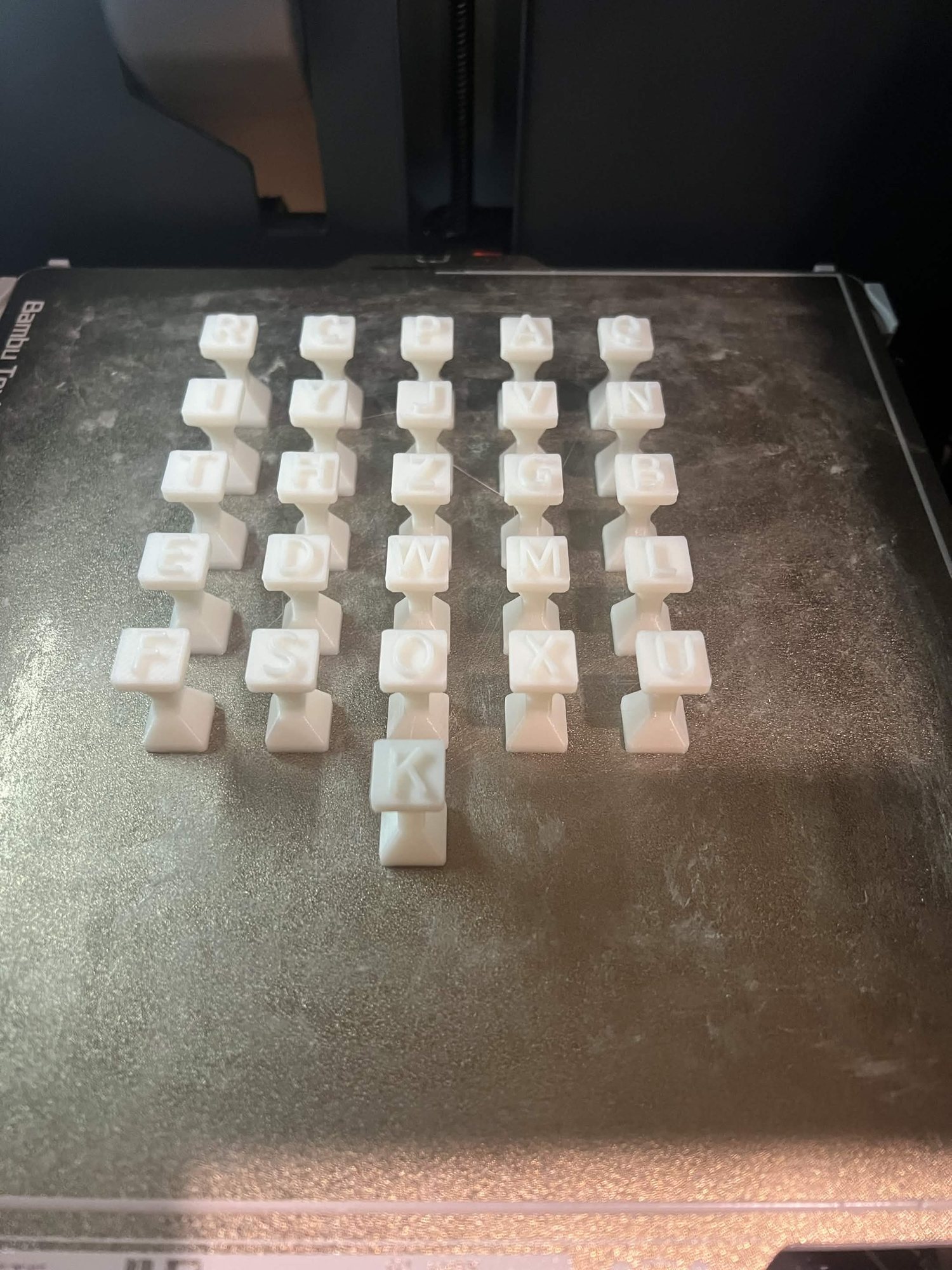
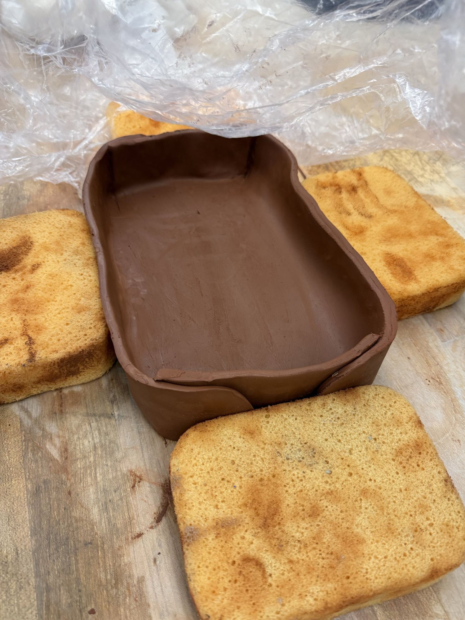
Over ten custom 3D-printed tools for ceramics classrooms — trimming tools, ribs, wire guides, and stamps. Each was iterated with students at Burlingame High School and published online for anyone with an FDM printer.
The ceramic tool set3D-printed loomClay-cutter stencil3D-printed A–Z & 0–9 stampsCasserole dish, cut with the clay-cutter
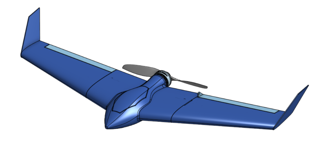
3D-Printed Plane
2023
A first attempt at designing and printing a flyable model plane — chasing the lightest airframe I could print that would still hold together. It didn't: the wing snapped at the root on the first flight. That joint is where the next version starts.
First airframe attempt
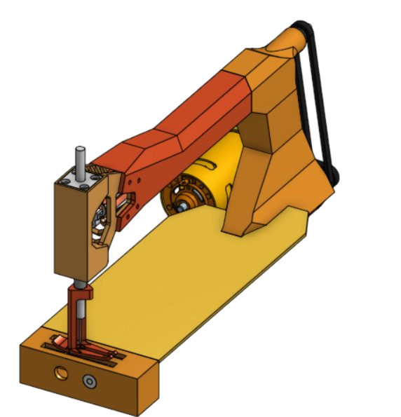
Sewing Machine (CAD)
2026
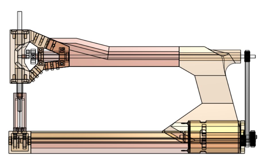
A full sewing machine modeled in CAD, from the outer housing down to the internal drive. I sew, so I wanted to understand how one motor shaft becomes a needle stroke, a feed step, and a bobbin rotation, all timed to each other.
Corner viewTranslucent side view — internal mechanism
Climbing Accessories
2026
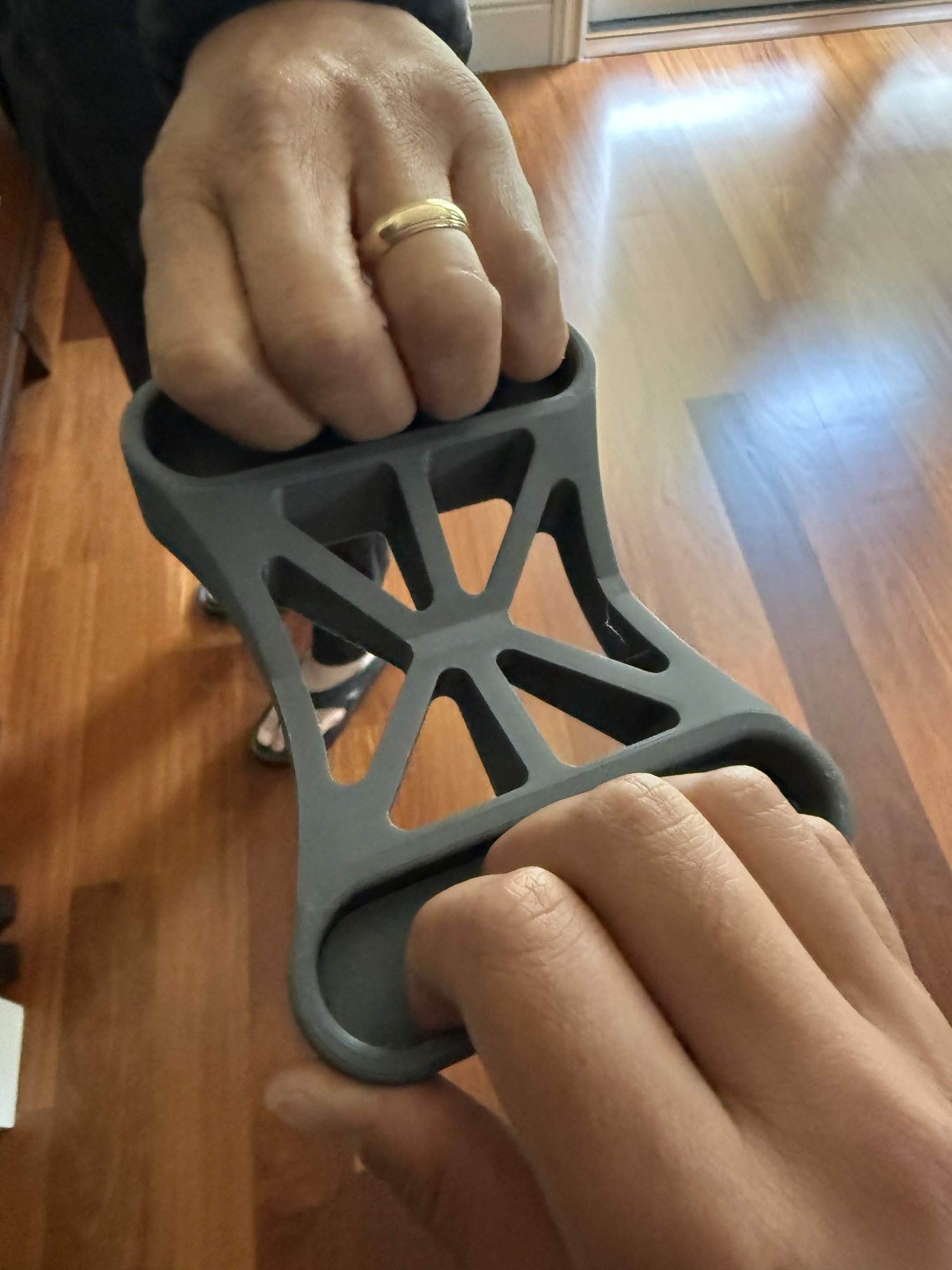
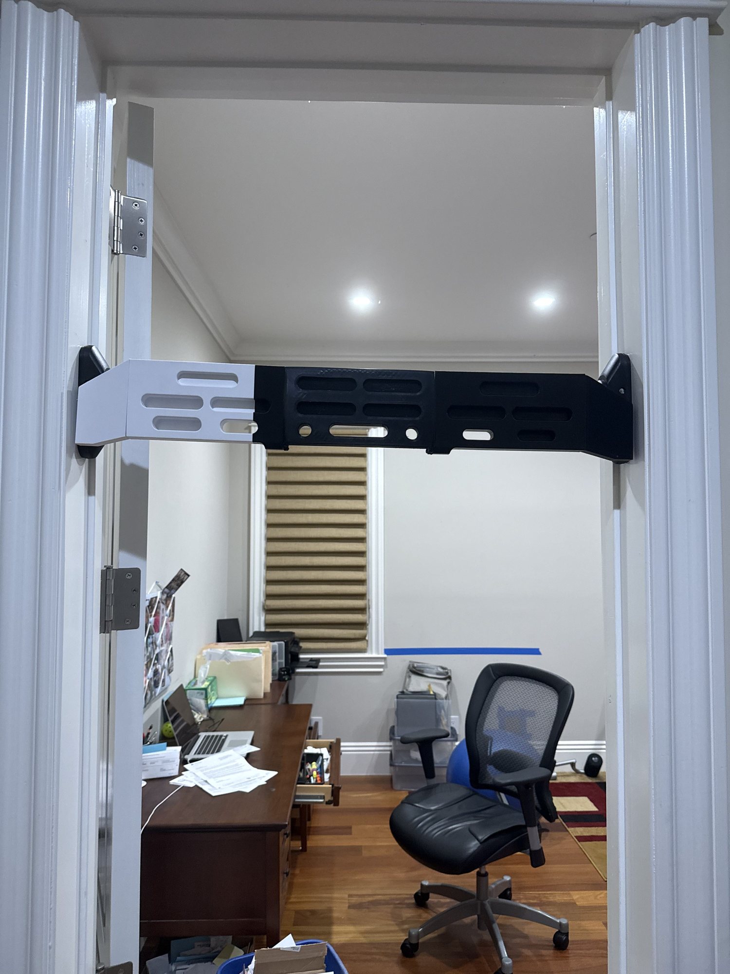
3D-printed gear I made for climbing. The Crimp Battle Board is a head-to-head crimp-strength game — two people pull on it to see who has the stronger crimp, and its X-rib lattice takes the abuse. The doorway hangboard is a printed grip trainer for building finger strength at home.
Testing crimp strength on the board3D-printed doorway hangboard — grip training
Kyle Tran
About
Engineer, builder, competitor
I'm a Mechanical Engineering student at Northeastern, originally from Burlingame, California. Reading about how something works has never been enough for me. I have to build one.
That's turned into combat robots, an autonomous survey boat, and a drawer full of 3D-printed ceramic tools. Whatever it is, the work runs the same way: sketch it in CAD, print the parts or send them out to be machined, wire it up, write the firmware, then break it and fix it until it holds. Combat robotics is where I learned to like that last part: losing, figuring out why, and coming back with the clock running.
Right now that's a catamaran that surveys water quality in local reservoirs on its own. Nobody handed me a manual for it. That's the part I like.
University
Northeastern
Major
Mechanical Eng.
Minor
Robotics
GPA
3.87
Graduating
May 2029
Based in
Burlingame, CA
Outside the lab
Hobbies & interests
Basketball
Pickup games whenever I can get one together — the outdoor courts at home, the gym on campus. I'll take a bad run over no run.
Climbing
Bouldering and top-rope, indoors and out. Read the problem, try something, fall, adjust — same as the workshop, with more chalk. I 3D-printed my own hangboard to train grip at home.
Designing & printing
A lot of my downtime looks like my work: modeling something in CAD and watching it print. Tools, fixtures, upgrades for other projects — if I can print a fix, I usually do.
Sewing
Mostly repairs and alterations — fixing what I own instead of replacing it. The one I keep coming back to is taking old jeans apart and sewing new ones out of the pieces. A pattern turns out to be a flat drawing of a 3D object, which felt familiar.
Teaching & mentoring
Explaining a thing is how I find out whether I actually understand it. These days that's mostly friends' print failures and wiring problems, and I still like it more than I expected to.
Browser games
Two games I built with AI coding agents rather than by hand, then put online — Hex Dominion, an idle hex-conquest game, and JSON, a much sillier one: a meme game about who, exactly, JSON is.
I build hardware end to end — CAD, composite layup, PCB design, firmware. The combat robots took me to 4th nationally and a top-15 U.S. ranking. The survey boat started as a sketch and drove itself to GPS waypoints on its first water test.
Oct 2023 — Jun 2025
President
Combat Robots Club, Burlingame
Ran workshops on CAD, soldering, physics, material science, and 3D printing. Handled sponsorships and club finances. The team placed on the podium 16 times — 4 firsts, 7 seconds, 5 thirds — across 5 competition events.
16 Podium Finishes5 EventsSponsorships Secured
Oct 2023 — May 2025
Ceramic Tools R&D
Burlingame High School · Ceramics Program
Researched, designed in CAD, and 3D-printed 10+ custom tools for the ceramics classes — trimming tools, ribs, wire guides, and stamps — then published them online for anyone to print.
10+ Tools publishedCAD → FDMOpen-sourced
Jan 2024 — May 2025
Secretary
Burlingame Aeronautics Club
Helped found the club and ran sessions on the physics of flight — aerodynamics, lift, and drag. Then put the theory into practice, designing small 3D-printed RC airplanes with carbon-fiber rods and lightweight print materials.
Co-foundedTaught aerodynamics3D-printed RC planes
Sep 2021 — May 2024
Subsystem Lead
Iron Panthers FRC #5026
Designed the spindexer mechanism for the team's competition robot. Worked with 10+ team members and 5 professional mentors on design reviews, manufacturing, and competition strategy.
Seeking a Summer 2027 co-op in hardware and robotics. I build robots, autonomous vehicles, and embedded systems — drawn in CAD, machined and printed, wired and coded, then tested until they hold up: two years of competitive combat robotics, and an autonomous survey boat built from scratch.
4thnationally, 2024
3.87GPA
10robots built
16team podiums
D.R.E.A.M.S v1 on the waterCreators' Showcase, NU LondonCombat robots — Team DHMMaze-navigating robot
A twin-hull autonomous survey boat, co-founded with Matthew Hong. V1, built in one semester in London, navigated to GPS waypoints on its own at St Katharine Docks and winched a sensor pod to the bottom to sample. V2 added a Raspberry Pi 5, stereo vision and our first custom PCB, but bench tests exposed flaws in its motor control, power and safety. V3, in build, pairs a Pi 5 with a Teensy 4.1 on a custom 4-layer carrier board. I lead the hardware; the software was built with AI coding agents.
Designed and built around ten robots that competed across five weight classes — weapon and drivetrain design, titanium and steel armor, composite layup, and iteration driven by what broke in the arena. 4th nationally in Plastic Antweight (2024), U.S. rankings of top-15, top-30, and top-35, and 4 firsts and 8 seconds at regional events; the club took 16 podiums over 5 events. The newest Achilles walks on a single-cam shuffler drive I designed.
Onshape · CNC-machined aluminum (outsourced) · laser-cut Ti / steel · brushless drive · FDM · DFM to a weight limit
Adaptive Compliant Robotic Arm
2026 – in design
A five-axis arm with a ±0.25° static target and a compliant TPU gripper that reads its own grip force. The base, shoulder and elbow run cycloidal gearboxes (14:1 to 22:1) with output-side magnetic encoders, and all three pass every check in a gearbox simulator I specified and built with AI coding agents. Nothing is built yet: a printed prototype comes first, then 7075 discs laser-cut by SendCutSend and finished on a Bantam PCB mill that I run.
A 3D-printed tank-drive robot, built with Matthew Hong for the Cornerstone of Engineering course at Northeastern, that completed all three challenge courses. I did the CAD, the printing and the MicroPython firmware: proportional steering off two angled ultrasonic sensors, with asyncio so the LCD and LEDs never stall the motors.
Onshape · 3D printing · MicroPython · asyncio · RP2040 · ultrasonic + IR · I2C LCD
Miscellaneous Builds
2023 – Present
10+ custom ceramics tools designed in CAD, printed, and open-sourced for anyone to print; 3D-printed RC aircraft with carbon-fiber spars; a full sewing machine reverse-engineered in CAD; and printed climbing hardware.
CAD to FDM · published on MakerWorld · github.com/ka1e27
Cornerstone of Engineering I · Statics · Thermodynamics · Materials Science · Probability & Statistics
Leadership experience
President
Oct 2023 – Jun 2025
Combat Robots Club, Burlingame
Ran workshops on CAD, soldering, physics, materials, and 3D printing; handled sponsorships and club finances. The team placed on the podium 16 times — 4 firsts, 7 seconds, 5 thirds — across 5 events.
Ceramic Tools R&D
Oct 2023 – May 2025
Burlingame High School · Ceramics Program
Modeled, printed, and published 10+ ceramics tools — trimming tools, ribs, wire guides, stamps — free on MakerWorld.
Secretary · Co-founder
Jan 2024 – May 2025
Burlingame Aeronautics Club
Helped found the club and taught the physics of flight — aerodynamics, lift, drag — then put it into practice designing 3D-printed RC aircraft.
Subsystem Lead
Sep 2021 – May 2024
Iron Panthers FRC #5026
Designed the spindexer mechanism for the competition robot, working with 10+ team members and 5 professional mentors through design reviews and manufacturing.
 01 · Survey boat

 03 · Robotic arm

 05A · Sewing

 04 · Maze robot
 02 · Combat

 05B · RC plane
 Catamaran bridge
Sensor winch
Catamaran bridge
Sensor winch